Calibrators
Calibration Adjustment
41
Calibration Adjustment Procedures (724 and 725)
The following sections detail the calibration procedures for the 724 and 725.
Cal Volts Input
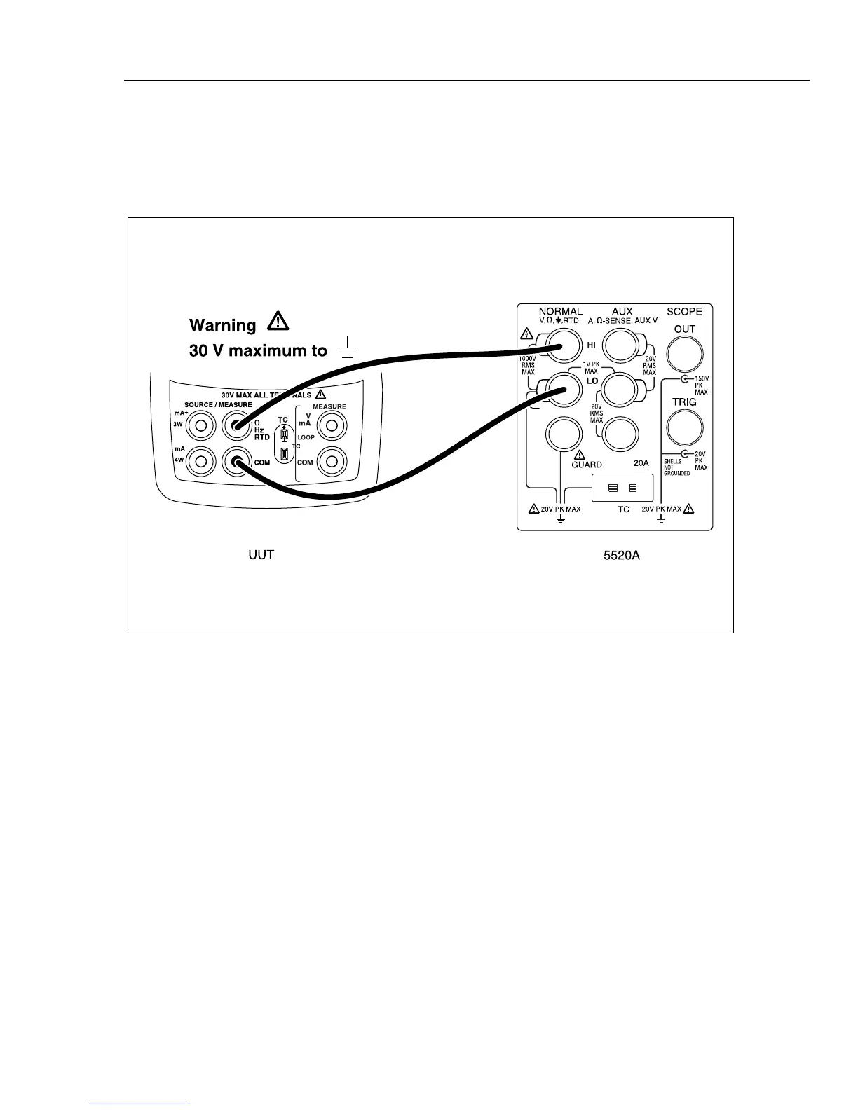
Connect the UUT as shown in Figure 13.
aal04f.eps
Figure 13. Volts Input Calibration Connections
From the Calibration Menu, type the cal step for Cal Volts Input. The PC displays:
Enter 0 Volts - press “ the proper key” to continue
Set the Fluke 5520A to output 0.0000 V, then press the space bar. After a short while, the
following calibration constant and prompt are displayed on the PC:
Offset = -40
Enter 10.00 Volts - press space bar to continue
Set the Fluke 5520A to output 10.0000 V, and press the space bar. After a short while,
the following calibration constants and prompt are displayed on the PC:
diff = (Counts - Offset)
3032676 = 3032636 - -40
Volts per count = 0.000003
- press space bar to continue
Press the space bar to return to the Calibration Menu.

 Loading...


