EasyManuals Logo

Fluke 724 Calibration Manual

Fluke 724
76 pages
To Next Page IconTo Next Page
To Previous Page IconTo Previous Page
Page #34 background imageLoading...
Page #34 background image
724/725/726
Calibration Manual
26
Lower Display mV/TC Measurement Tests
1. Press RESET on the 5520A.
2. Press V on the UUT until MEASURE and mV appear on the lower display.
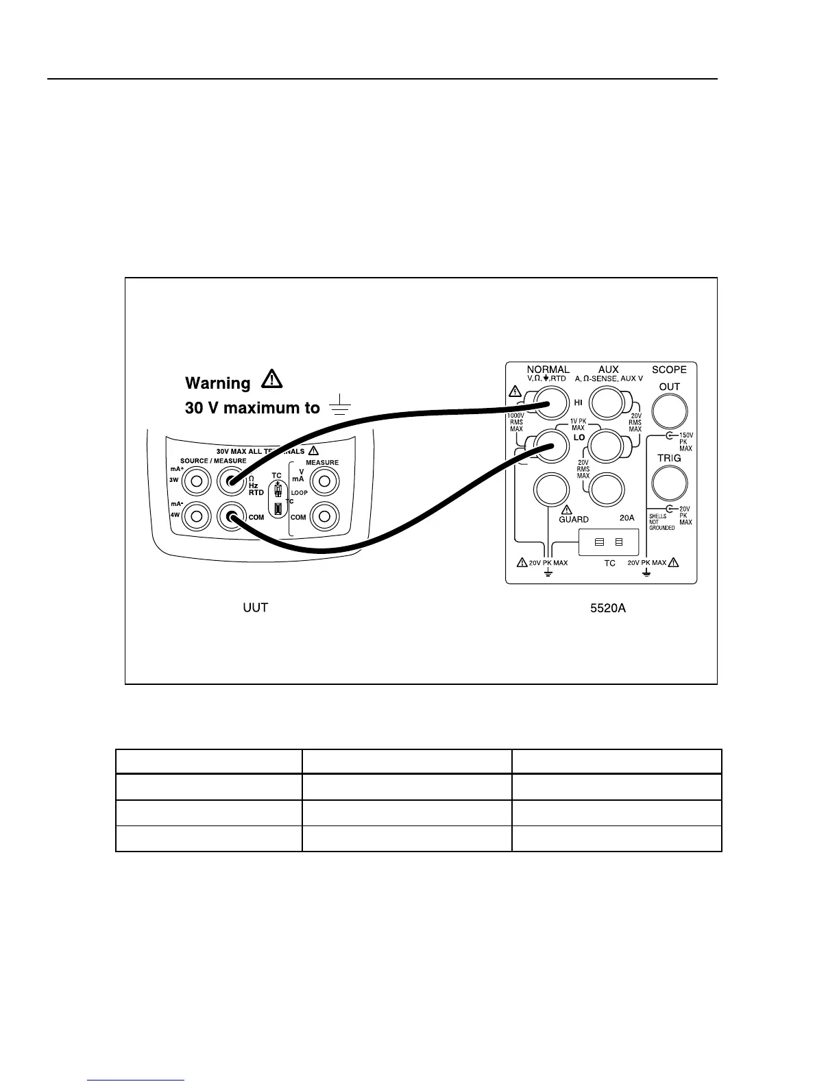
3. Make the connections shown in Figure 3.
4. Set up the 5520A to output each of the voltages in Table 8 and verify that the UUT
readings are within the limits shown.
5. Press STBY on the 5520A.
aal04f.eps
Figure 3. Lower Display mV and Voltage Test Connections
Table 8. Lower Display mV Readings
5520A Outputs 724/725 UUT Readings 726 UUT Readings
0.00 mV -0.02 mV to +0.02 mV -0.0100 mV to +0.010 mV
45.00 mV 44.97 mV to 45.03 mV 44.986 mV to 45.014 mV
90.00 mV 88.96 mV to 89.04 mV 88.981 mV to 89.019 mV

Table of Contents

Other manuals for Fluke 724

Questions and Answers:

Question and Answer IconNeed help?

Do you have a question about the Fluke 724 and is the answer not in the manual?

Fluke 724 Specifications

General IconGeneral
Temperature Range-10°C to 55°C
Thermocouple TypesJ, K, T, E, R, S, B, L, U, N
Current Measurement0 to 24 mA
Operating Temperature-10°C to 55°C
FunctionProcess calibrator
RTD TypesPt100, Pt500, Pt1000
Voltage Measurement0 to 10 V
Loop Power24 V DC
DisplayDual Display
Power Supply4 AA batteries
Resolution0.1 °C
Storage Temperature-20 °C to 60 °C
Battery Life25 hours
Relative Humidity0 % to 90 %
Safety ComplianceCSA C22.2 No. 1010.1:1992

Related product manuals