724/725/726
Calibration Manual
32
Lower Display 4-Wire Resistance Measurement Tests
1. Press F on the UUT (Ron 726) until Ω appears on the lower display. If
necessary, use M to get to the measure mode, and use X )to get to the 4W mode.
(MEASURE should also appear on the lower display).
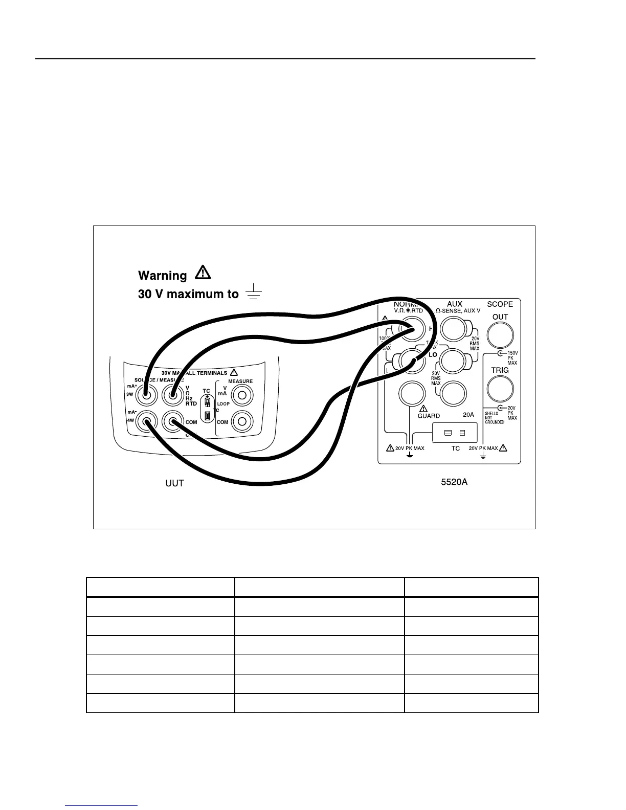
2. Set the 5520A to 2-wire output with 2-wire compensation off; then make the
connections shown in Figure 8.
3. Set the 5520A to source the resistance values in Table 12 and verify that the UUT
resistance readings are within the limits shown.
4. Press STBY on the 5520A.
aal09f.eps
Figure 8. Lower Display 4-Wire Resistance Test Connections
Table 12. Lower Display 4-Wire Resistance Readings
5520A Outputs 724/725 UUT Readings 726 UUT Readings
15.00 Ω 14.90 Ω to 15.10 Ω 14.94 Ω to 15.06 Ω
350.00 Ω 349.90 Ω to 350.10 Ω 359.90 Ω to 350.10 Ω
500.00 Ω 499.5 Ω to 500.5 Ω 499.375 Ω to 500.625 Ω
1500.0 Ω 1499.5 Ω to 1500.5 Ω 1499.2 Ω to 1500.8 Ω
3200.0 Ω 3199.0 Ω to 3201.0 Ω -
3800.0 Ω - 3798.9 Ω to 3801.1 Ω

 Loading...


