EasyManuals Logo

Fluke 724 Calibration Manual

Fluke 724
76 pages
To Next Page IconTo Next Page
To Previous Page IconTo Previous Page
Page #38 background imageLoading...
Page #38 background image
724/725/726
Calibration Manual
30
Lower Display Frequency Measurement Test (725 and 726)
1. Set the 5520A to source a 10 kHz, 1 V peak-to-peak square wave (use the blue
softkey under the wave type to change the wave shape).
2. Press F on the UUT (Kfor 726) until MEASURE and kHz appear on the
lower display.
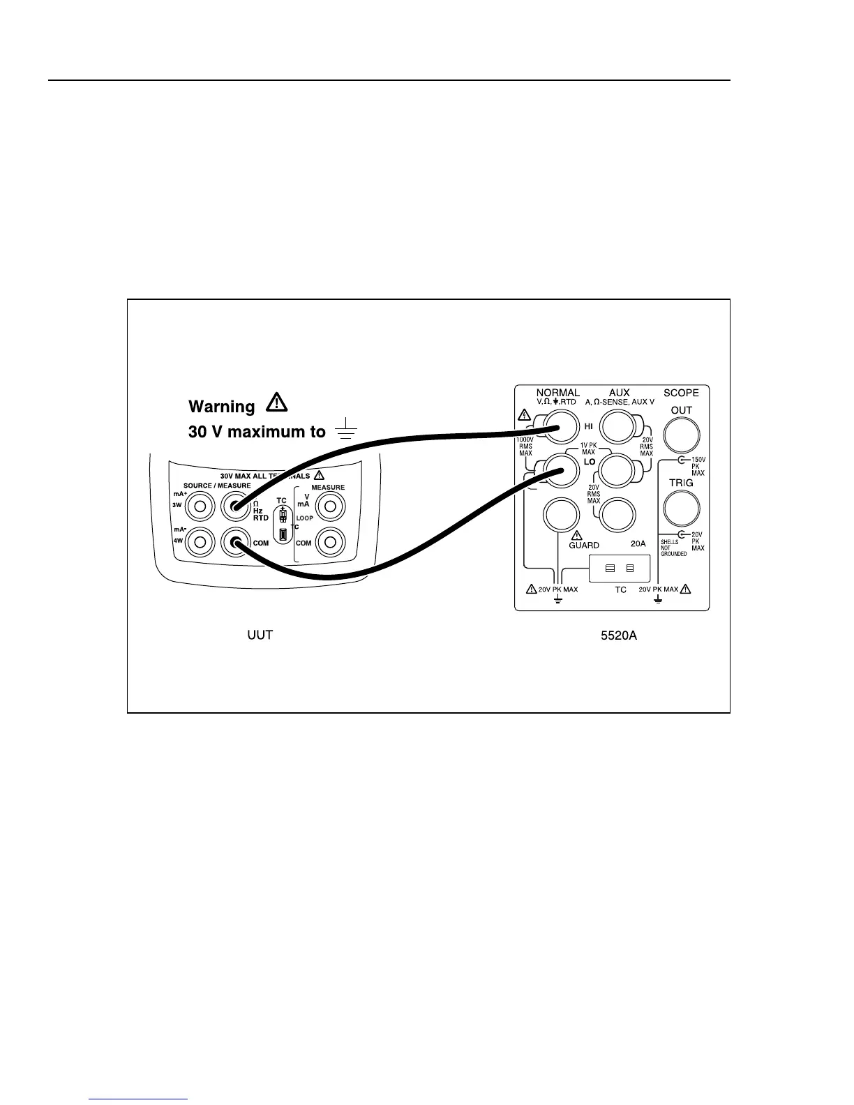
3. Make the connections shown in Figure 6.
4. Verify that the UUT frequency reads between 9.98 kHz and 10.02 kHz.
5. Press STBY on the 5520A.
aal04f.eps
Figure 6. Lower Display Frequency Test Connections

Table of Contents

Other manuals for Fluke 724

Questions and Answers:

Question and Answer IconNeed help?

Do you have a question about the Fluke 724 and is the answer not in the manual?

Fluke 724 Specifications

General IconGeneral
Temperature Range-10°C to 55°C
Thermocouple TypesJ, K, T, E, R, S, B, L, U, N
Current Measurement0 to 24 mA
Operating Temperature-10°C to 55°C
FunctionProcess calibrator
RTD TypesPt100, Pt500, Pt1000
Voltage Measurement0 to 10 V
Loop Power24 V DC
DisplayDual Display
Power Supply4 AA batteries
Resolution0.1 °C
Storage Temperature-20 °C to 60 °C
Battery Life25 hours
Relative Humidity0 % to 90 %
Safety ComplianceCSA C22.2 No. 1010.1:1992

Related product manuals