EasyManuals Logo

Fluke 724 Calibration Manual

Fluke 724
76 pages
To Next Page IconTo Next Page
To Previous Page IconTo Previous Page
Page #72 background imageLoading...
Page #72 background image
724/725/726
Calibration Manual
64
Calibrating Thermocouple mV Output
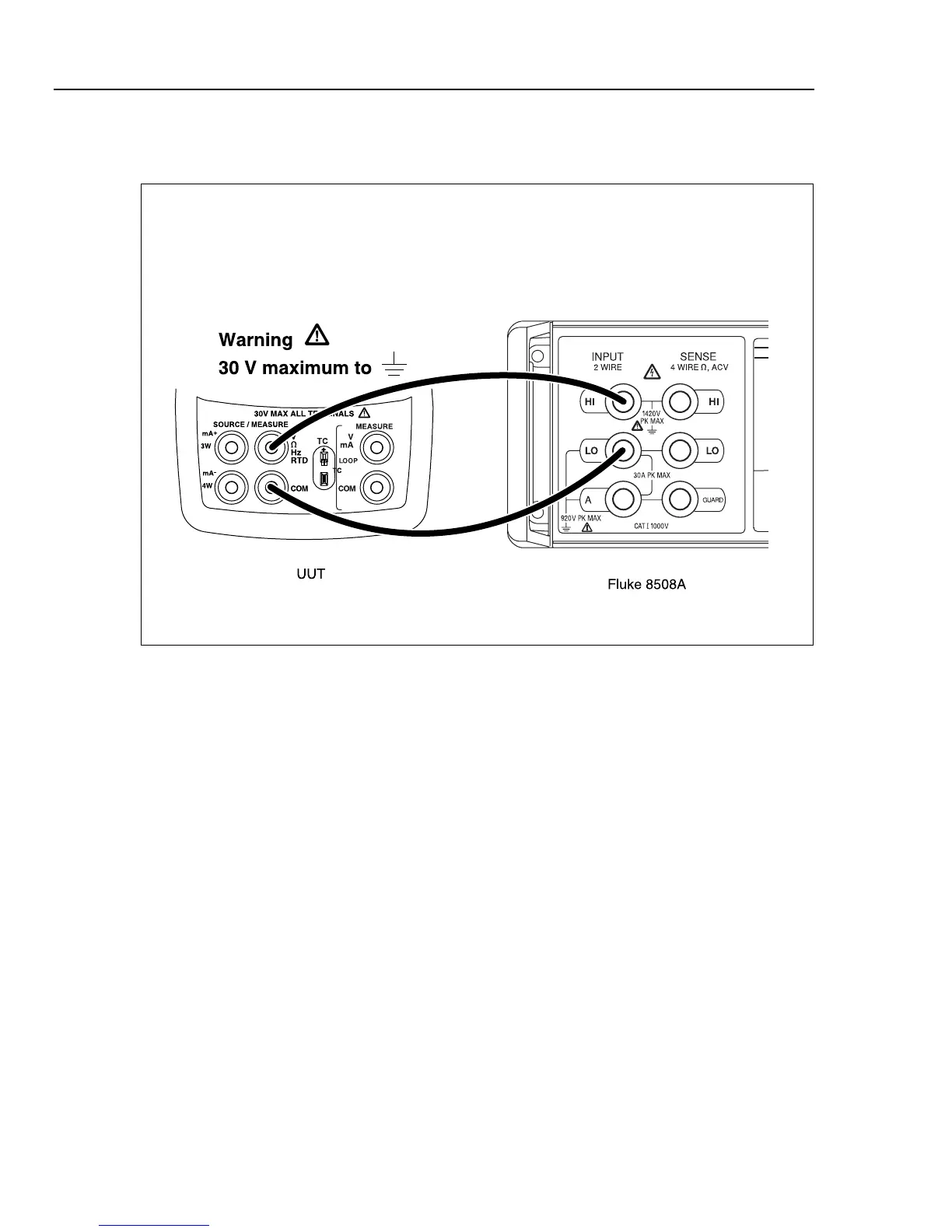
Connect the UUT as shown in Figure 33.
aal08f.eps
Figure 33. Thermocouple mV Output Calibration Connections
After making the proper connections, type “10” then press the Enter key on the PC
keyboard. Input directions are displayed at the bottom of the calibration menu:
Enter Selection:
First Calibration Point. Enter mV displayed:
Second Calibration Point. Enter mV displayed:
Use the 8508A to measure the two calibration points. Enter each of the two calibration
points as prompted.

Table of Contents

Other manuals for Fluke 724

Questions and Answers:

Question and Answer IconNeed help?

Do you have a question about the Fluke 724 and is the answer not in the manual?

Fluke 724 Specifications

General IconGeneral
Temperature Range-10°C to 55°C
Thermocouple TypesJ, K, T, E, R, S, B, L, U, N
Current Measurement0 to 24 mA
Operating Temperature-10°C to 55°C
FunctionProcess calibrator
RTD TypesPt100, Pt500, Pt1000
Voltage Measurement0 to 10 V
Loop Power24 V DC
DisplayDual Display
Power Supply4 AA batteries
Resolution0.1 °C
Storage Temperature-20 °C to 60 °C
Battery Life25 hours
Relative Humidity0 % to 90 %
Safety ComplianceCSA C22.2 No. 1010.1:1992

Related product manuals