19
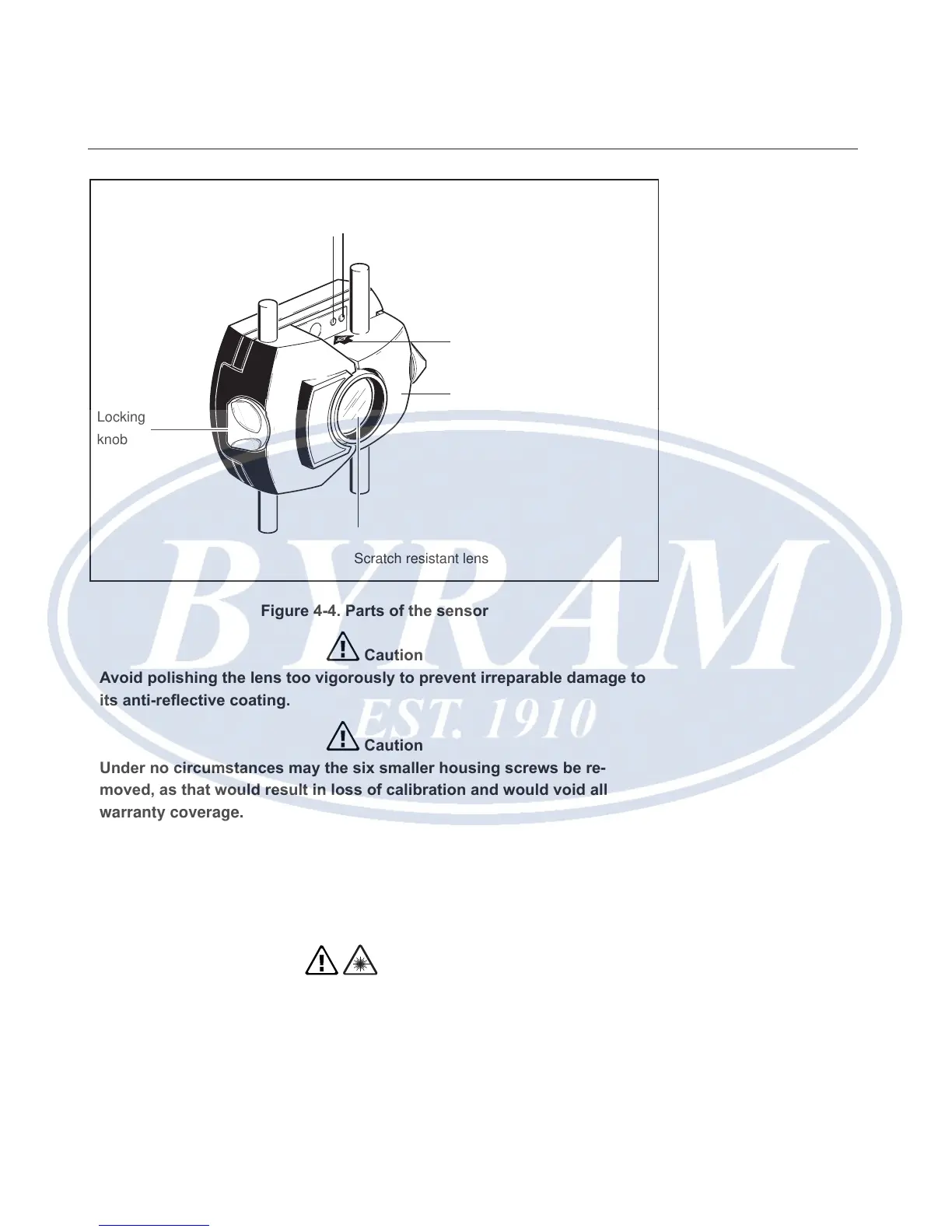
Figure 4-4. Parts of the sensor
Caution
Avoid polishing the lens too vigorously to prevent irreparable damage to
its anti-reective coating.
Caution
Under no circumstances may the six smaller housing screws be re-
moved, as that would result in loss of calibration and would void all
warranty coverage.
Note
The calibration accuracy of the sensor should be checked every two years as
indicated by the colored label located on the back of the sensor housing. Please
return the sensor to your authorized service center for calibration checking.
Warning
Do not stare into the beam.
Scratch resistant lens
Housing mark = center of
bracket posts
Red LED indicates sensor is
powered and laser is on
Green LED indicates
beam adjustment
laser is on
IP 67 housing
Locking
knob
Overview
Sensor