55
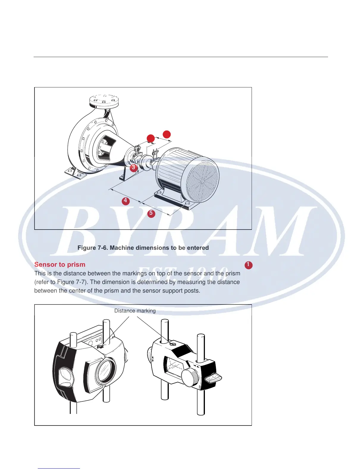
Enter dimensions as shown in Figure 7-6:
Figure 7-6. Machine dimensions to be entered
Sensor to prism
This is the distance between the markings on top of the sensor and the prism
(refer to Figure 7-7). The dimension is determined by measuring the distance
between the center of the prism and the sensor support posts.
Figure 7-7. Distance marking on the sensor and prism
1
2
3
4
5
1
Distance marking
Horizontal shaft alignment
Enter dimensions