128
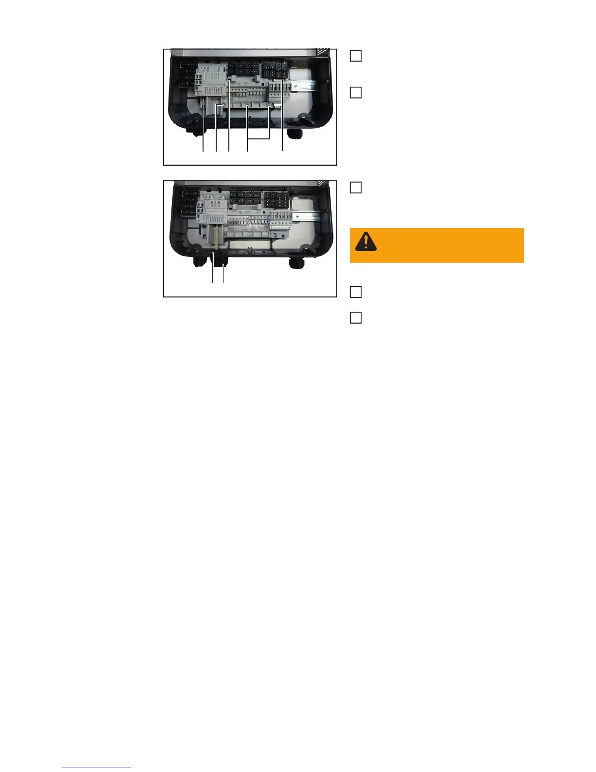
Insert the new DC disconnector and
secure it with four 4x9 TX20 screws (4)
[2 Nm]
Fix the strain relief clamp using three
4x20 TX20 screws (3)
[3-4 turns]
Insert the control switch and shaft (2)
and secure it with the retaining clip (1)
Connect the AC and DC lines to the
terminal block of the DC disconnector
Place the inverter in the wall bracket
(see "Opening and closing the device")
(4) (4)
(3)(3)(4)
1
2
(1)(2)
WARNING! Take safety precau-
tions. Observe the safety rules -
DC voltage present!
3
5
6