163
EN
However, on the DC disconnector, the measurements should only be taken at the screws,
not the contacts.
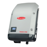
1 Measuring device
2 Inverter
9 Measuring line
Examples of measuring the insulation resistance.
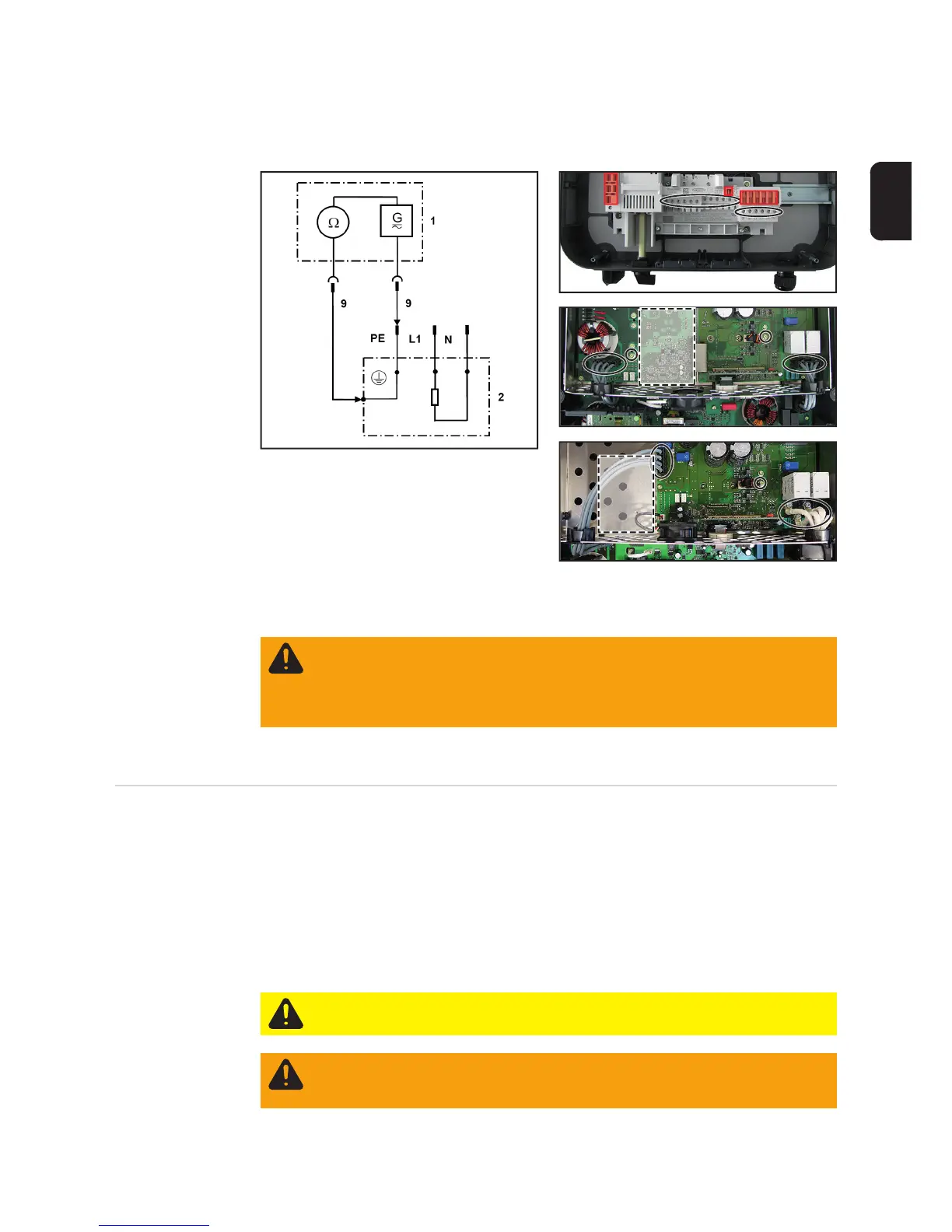
Overvoltage PC board (5)
Capacitor discharge time is at least 6 min.
Ground conduc-
tor resistance
- Only perform the measurement if the insulation resistance test produced an accept-
able result.
- Fit the cover back onto the inverter.
- Correct functioning of the ground conductor is only guaranteed if the results of the
measurement between the cover and the wall bracket are acceptable.
- The device being tested must be safely isolated from the AC grid (the grid lead [L, N]
must not be connected). If the AC grid cannot be disconnected from the wall bracket,
the relevant safety precautions must be taken.
- Place the inverter back in the wall bracket.
Ground to AC / Ground to DC
Symo 10-20, Eco
Symo 10-20
Eco
(5)
(5)
WARNING! An electric shock can be fatal. Capacitors can charge during the in-
sulation resistance measurement. After carrying out the insulation resistance test,
check that all tested potentials are de-energised before continuing with the safety
inspection. Alternatively, the capacitors can be discharged by short-circuiting the
tested potentials or via the discharge function on the insulation tester.
CAUTION! Take safety precautions. Observe the safety rules - DC voltage pres-
ent!
WARNING! Set the inverter DC disconnector to the 0 position and place the in-
verter in the wall bracket. Placing the inverter in the wall bracket causes a voltage
to be applied to the inverter.