127
EN
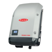
Insert the control switch and shaft (2)
and secure it with the retaining clip (1)
Connect the AC and DC lines to the
terminal block of the DC disconnector
Place the inverter in the wall bracket
(see "Opening and closing the device")
Replacing the DC
disconnector Eco
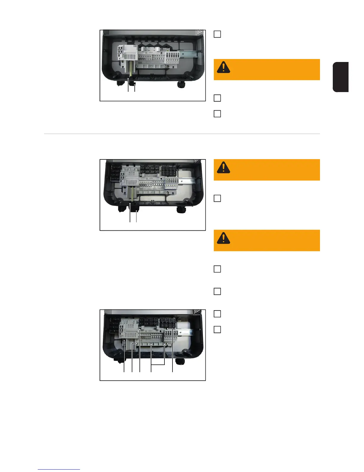
Removing the DC disconnector:
Remove the inverter from the wall bra-
cket (see "Opening and closing the de-
vice")
Disconnect the AC and DC leads from
the terminal block of the DC dis-
connector
Remove the retaining clip (1) and con-
trol switch with shaft (2)
Undo the three 4x20 TX20 screws (3)
and remove the strain relief clamp
Undo the four 4x9 TX20 screws (4) and
remove the DC disconnector
Inserting the DC disconnector:
(1)(2)
WARNING! Take safety precau-
tions. Observe the safety rules -
DC voltage present!
3
5
6
(1)(2)
WARNING! Observe the safety
rules (see the beginning of the
"Safety" section)
WARNING! Take safety precau-
tions. Observe the safety rules -
DC voltage present!
1
2
3
(4) (4)
(3)(3)(4)
4
5