94
Function overview
Device concept
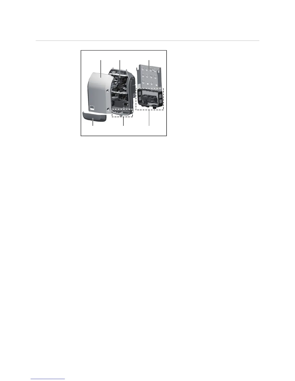
Device design:
(1) Housing lid
(2) Inverter
(3) Wall bracket
(4) Connection area incl. DC main
switch
(5) Data communication area
(6) Data communication cover
The inverter converts the direct current cre-
ated in the solar modules into alternating
current. This alternating current is fed into
the public grid synchronously with the grid
voltage.
The inverter has been developed exclusively for use in grid-connected photovoltaic sys-
tems; it is impossible to generate energy independently of the public grid.
Thanks to its design and the way it works, the inverter is extremely safe both to install and
to operate.
The inverter automatically monitors the public grid. In the event of abnormal grid condi-
tions, the inverter ceases operating immediately and stops feeding power into the grid (e.g.
if the grid is switched off, if there is an interruption, etc.).
Grid monitoring involves monitoring voltage, frequency and the stand-alone situation.
The inverter operates fully automatically. As soon after sunrise as there is sufficient energy
available from the solar modules, the inverter starts monitoring the grid. When insolation
has reached a sufficient level, the inverter starts feeding energy into the grid.
The inverter operates in such a way that the maximum possible amount of power is ob-
tained from the solar modules.
As soon as the power available has fallen below the level at which energy can be fed into
the grid, the inverter disconnects the power electronics completely from the grid and stops
running. It retains all its settings and stored data.
If the inverter becomes too hot, it automatically reduces the current output power in order
to protect itself.
Reasons for the inverter becoming too hot include the ambient temperature being too high
or inadequate heat dissipation (e.g. if it is installed in a switch cabinet without suitable heat
dissipation).
The Fronius 15.0 does not have an internal boost converter. This results in certain restric-
tions in the choice of solar module and string. The minimum DC input voltage (U
DC min
)
depends on the grid voltage. On the other hand, a highly optimised device is then available
for the appropriate application.
(1) (2) (3)
(4)(5)(6)