135
EN
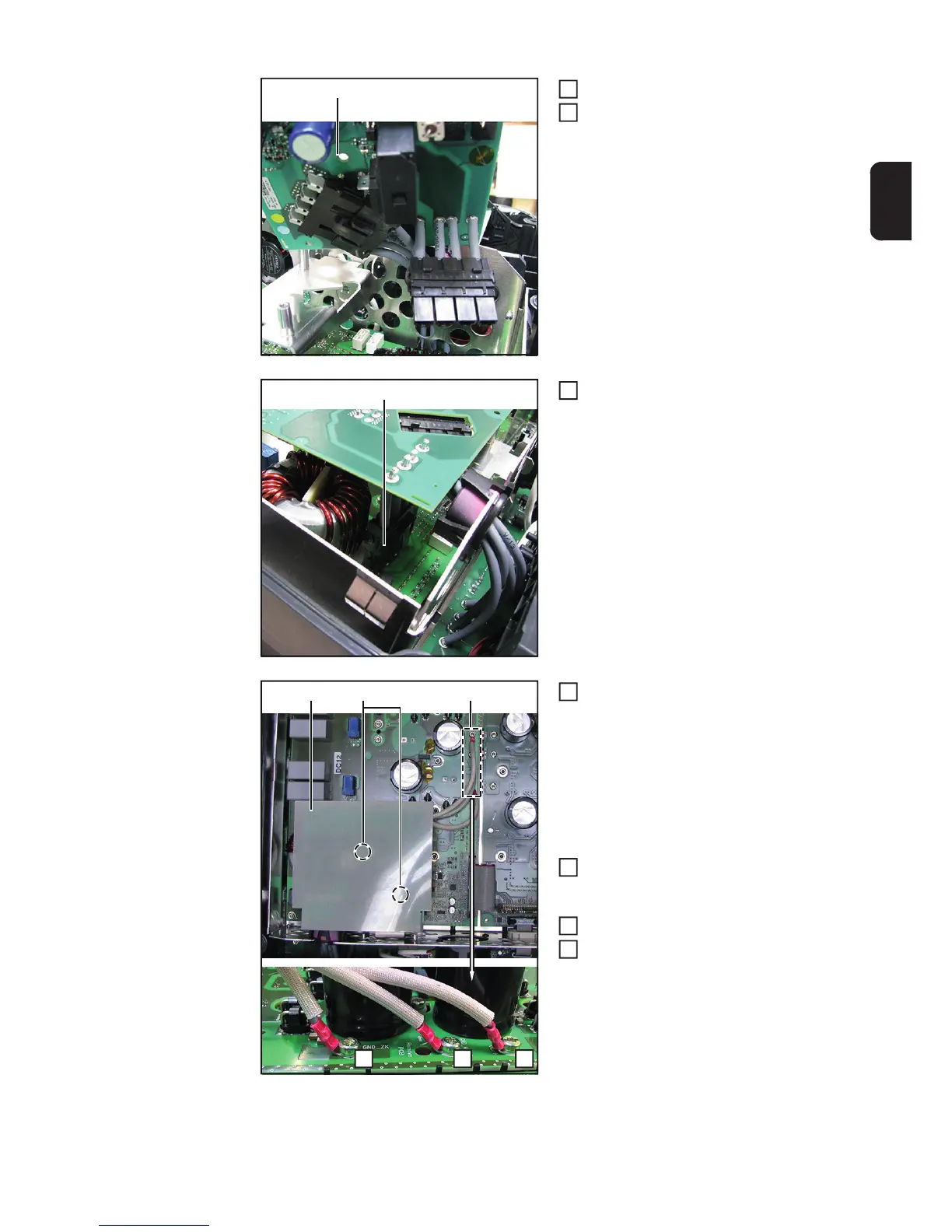
Insert the overvoltage PC board
Establish a connection to the OVP (5)
Establish cable connection (4)
Mount the new overvoltage PC board
with two 4x9 TX20 screws (3)
[2 Nm]
Mount cable connection (2) with three
4x9 TX20 screws
[2 Nm]
Insert insulating sheet (1)
Close the inverter and place it into the
wall bracket (see “Opening and closing
the device“ section)
(5)
3
4
(4)
5
(2)(3)(1)
A B C
IMPORTANT! Make sure that cable con-
nections A (short), B (medium) and C (long)
are bent in such a way they point away from
the PC board (see illustration)
6
7
8
9