148
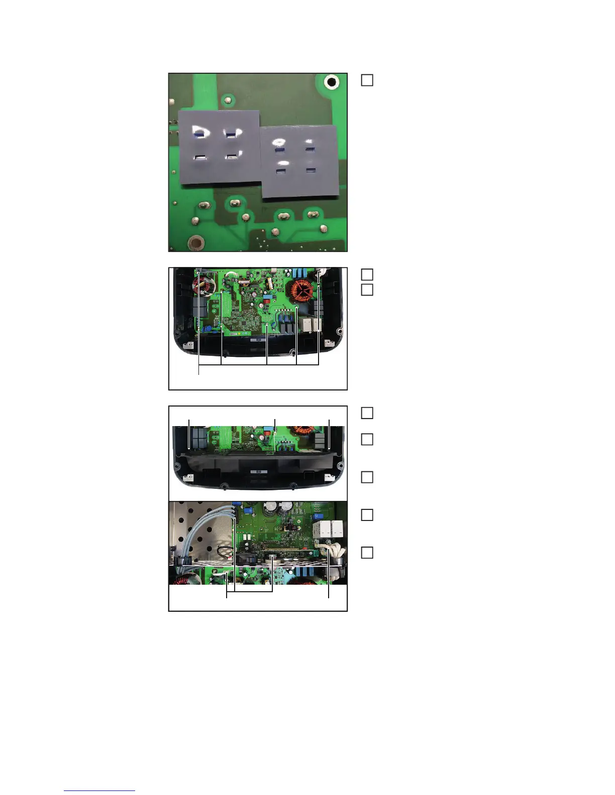
Inserting the EcoFIL:
Remove the protective film from the
thermally conductive pad fort he new
EcoFil PC board and ensure that the
pads do not slip out of place or fall off
during installation.
Thread in and position the new EcoFIL
Fit the EcoFIL with nine 4x9 TX20
screws (5)
[2 Nm]
Connect all cables and plug connec-
tions (3) to the EcoFIL
Fit the Datcom insert with two 5x10
TX25 screws (2)
[1.2 Nm]
Fit the ground connection with a 4x9
TX20 screw (1)
[2 Nm]
Fit the AC cable harness with four 5x10
TX20 screws (4)
[3.5 Nm]
Insert the Recerbo, close the inverter
and place it in the wall bracket (see
"Replacing the display PC board -
Recerbo", "Opening and closing the
device" and necessary „Replacing the
Overvoltage PC board“ sections)
Switch on the inverter and then carry out a
fan test via the display (see operating inst-
ructions)
1
(5)
2
3
(2)(2) (1)
(3) (4)
4
5
6
7
8