150
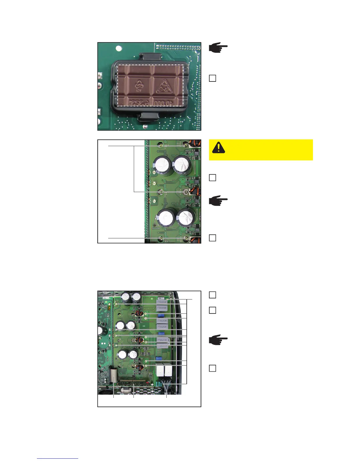
Inserting the SymoPS AC:
Detach the blister packs from the new
SymoPS AC at the tabs and place
them on the faulty SymoPS AC
Insert the new SymoPS AC and positi-
on accordingly
Fit the SymoPS AC solar modules with
six 4x9 TX20 screws (4). Observe the
torque sequence to avoid applying me-
chanical stress
First pretension all six screws to [0.5
Nm] and then tighten them to [2 Nm]
Thread in and connect all cables and
plug connections (1-2)
Fit the SymoPS AC with twelve 4x9
TX20 screws (3)
[2 Nm]
Close the inverter and place it in the
wall bracket (see "Opening and closing
the device")
Switch on the inverter and then carry out a
fan test via the display (see operating inst-
ructions)
NOTE! Do not press on the
marked area -> this will damage
the PCM material
1
(4)
(4)
CAUTION! The PCM paste must
not be damaged or removed when
inserting the SymoPS AC
NOTE! To avoid applying me-
chanical stress to the solar mod-
ules, apply the torque in the same
sequence
2
3
(3)
(1) (1)(2)
NOTE! Ensure that the ferrite
cores and their holders are fitted
correctly
4
5
6