152
Detach the blister packs from the new
SymoPS DC at the tabs and place
them on the faulty SymoPS DC
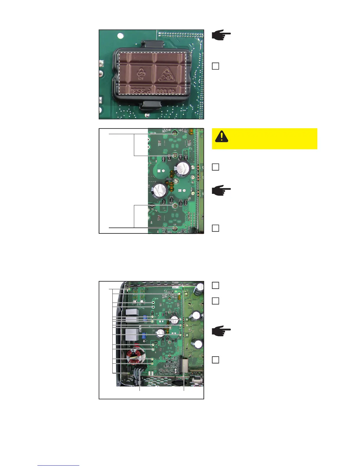
Insert the new SymoPS DC and positi-
on accordingly
Fit the SymoPS DC solar modules with
four 4x9 TX20 screws (3). Observe the
torque sequence to avoid applying me-
chanical stress
First pretension all four screws to [0.5
Nm] and then tighten them to [2 Nm]
Thread in and connect all cables and
plug connections (1)
Fit the SymoPS DC with 13/15 4x9
TX20 screws (2)
[2 Nm]
Close the inverter and place it in the
wall bracket (see "Opening and closing
the device" and necessary „Replacing
the Overvoltage PC board“ sections)
Switch on the inverter and then carry out a
fan test via the display (see operating inst-
ructions)
NOTE! Do not press on the
marked area -> this will damage
the PCM material
1
(3)
(3)
CAUTION! The PCM paste must
not be damaged or removed when
inserting the SymoPS DC
NOTE! To avoid applying me-
chanical stress to the solar mod-
ules, apply the torque in the same
sequence
2
3
(2)
(1)(1)
NOTE! Ensure that the ferrite
cores and their holders are fitted
correctly
4
5
6