MHT258a (Engl.)6-16
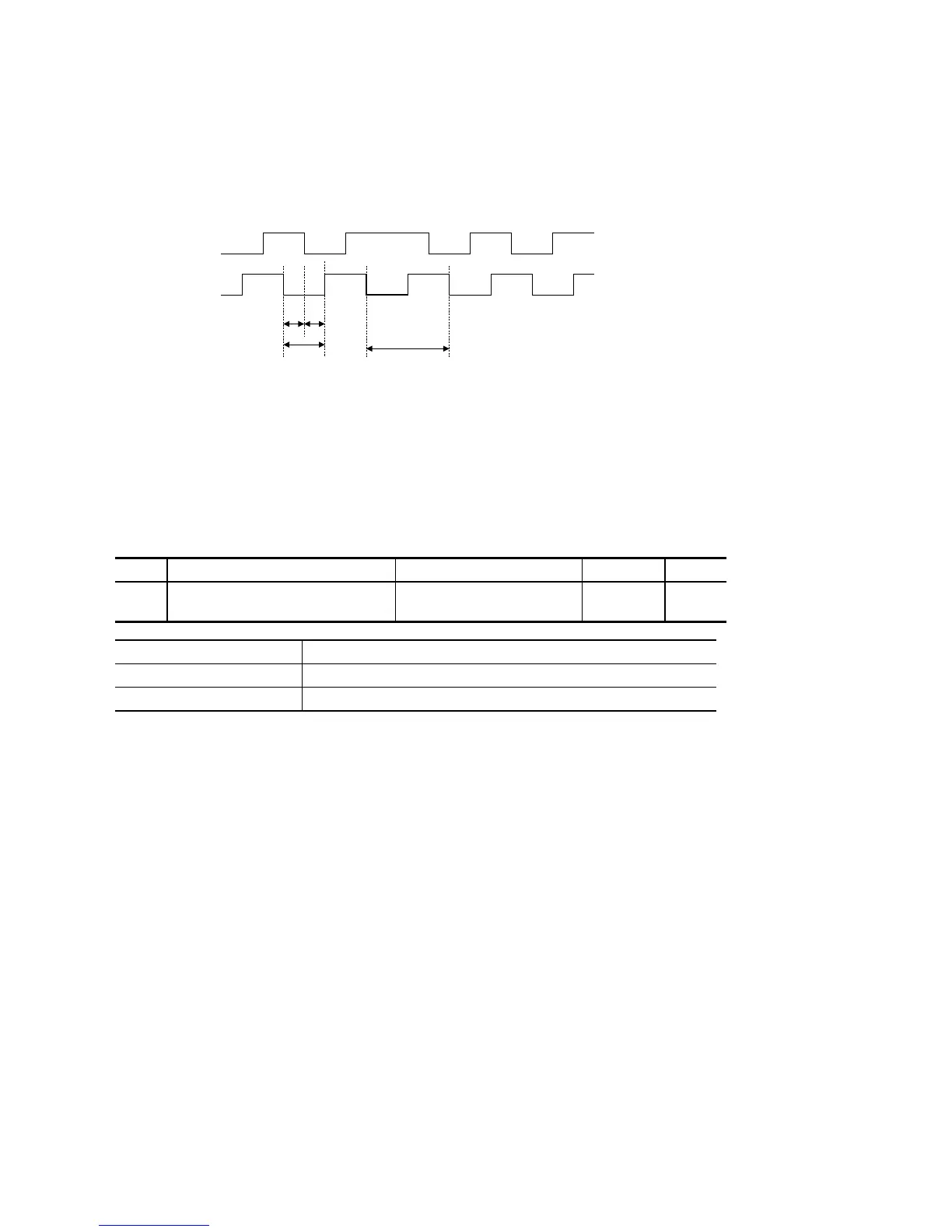
■ Two 90° phase-different signal
A-phase and B-phase signal indicate rotational direction and rotational quantity, respectively.
Each edge of A-phase and B-phase signals corresponds to one pulse.
A-phase
[CA]
B-phase
[CB]
t
10
t
8
t
9
Pulse width : t
8
>
1.25
μ
s
Pulse cycle : t
9
≧
2.5
μ
s
Edge interval : t
10
>
1.25
μ
s
6.2.5 Braking resistor
Connects the NTC thermistor of braking resistor to the control input terminal to protect the resistor.
System parameter 86
Para. Name Setting range Initial value Change
86 Braking resistor thermal overload relay 0: Electronic thermal O/L relay
1: External thermal O/L relay
0 Power
Setting Overheat detection of braking resistor
0: Electronic thermal O / L relay Calculates the regenerated power by amplifier to protect the resistor.
1: External thermal O / L relay Directly detects resistor overheat using NTC thermistor built-in the resistor.
To use external thermal relay, set the external alarm input (34) at the control allocation terminal, connect NTC thermistor for the external
resistor.
Protective function by electronic thermal relay built-in the amplifier will be disabled.
 Loading...