LED name LED status Meaning
CACHE
(green)
There is data in the cache memory of the ETERNUS DX.
READY
(green) (*1)
The ETERNUS DX is available for use.
*1: When the READY LED and the FAULT LED are both on at the same time, an error has occurred while the Unified configuration is
starting up.
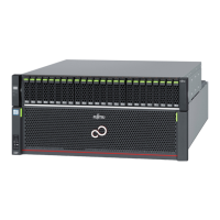
● ETERNUS DX500 S5/DX600 S5
An operation panel has LEDs, a Power switch, and setting change switches.
Figure 31 Operation Panel (Controller Enclosure for the ETERNUS DX500 S5/DX600 S5)
1
2 4
3
With a fr
ont cover Without a front cover
POWER LED
IDENTIFY LED
FAULT LED
MAINTENANCE LED CACHE LED
READY LED REMOTE LED
1 Power switch
This switch is used to turn on or off the ETERNUS DX.
2 MNT SW (maintenance switch)
This switch is used to switch the maintenance status on or off.
3 IP RST SW (IP reset switch)
This switch is used to initialize the LAN ports or to initialize the user information.
4 MST SW (CM Master Change switch)
This switch is used to change the Master CM.
The LEDs turn on or blink to indicate the statuses that are listed below.
Table 15 Status and Meaning of Each LED (Operation Panel [Controller Enclosure for the ETERNUS DX500
S5/DX600 S5])
LED name LED status Meaning
POWER
(green)
Power is supplied to the controller enclosure.
IDENTIFY
(blinks blue)
The installation location of the controller is identified according to
the instruction that is issued from ETERNUS Web GUI or ETERNUS CLI.
A. Component Names
Controller Enclosure
106 Operation Guide (Basic)
 Loading...