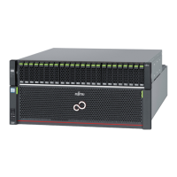
● ETERNUS DX900 S5
Figure 40 Controller (ETERNUS DX900 S5)
DI (OUT) LINK/FAULT LED
FRT FAULT LED
FRT READY LED
READY/FAULT LED MASTER LED
BUD READY LED
BUD FAULT LED
SVC READY LED
S
VC FAULT LED
LAN ACT LED
L
AN LINK LED
IDENTIFY LED
The LEDs turn on or blink to indicate the statuses that are listed below.
Table 21 Status and Meaning of Each LED (Controller for the ETERNUS DX900 S5)
LED name LED status Meaning
READY/FAULT
(green)
The controller is in normal status.
(blinks green)
An error has occurred during startup.
(amber)
• The controller is in error status.
• An error has occurred during startup.
(blinks amber)
IDENTIFY
(blinks blue)
The installation location of the controller is identified according to
the instruction that is issued from ETERNUS Web GUI or ETERNUS CLI.
LAN LINK
(green)
The link between the LAN port and the destination port has been
established.
LAN ACT
(blinks green)
Data is being sent or received via the LAN port.
MASTER
(green)
The controller is set as a Master CM.
DI (OUT) LINK/FAULT
(green)
The link between the DI (OUT) port and the destination port has been
established.
(amber)
• The link between the DI (OUT) port and the destination port is in
error status.
• The ports to remove the cables between enclosures from are
indicated. This occurs while a drive enclosure is being added.
(blinks amber)
The ports to connect the cables are indicated. This occurs while a
drive enclosure is being added.
BUD READY
(green)
The BUD is in normal status.
A. Component Names
Controller Enclosure
113 Operation Guide (Basic)
 Loading...