100
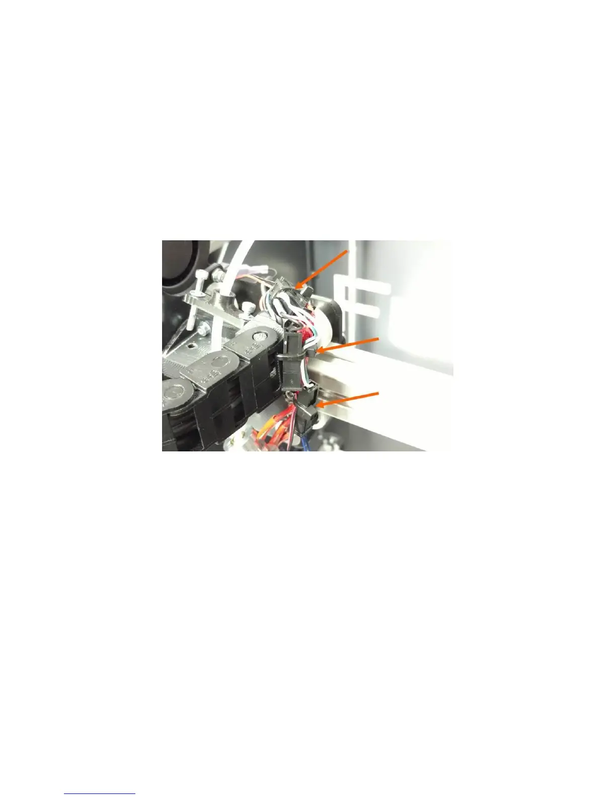
Retain the wires with zip ties so the wiring looks similar to how it looked when you cut the originals:
One zip tie should hold the thermistor connector to the heater cartridge wires (thick red). The
thermistor leads (small blue) should have a small amount of slack between the connector and
the print head block.
The next zip tie retains the thermistor leads, the heater leads, and the 30mm fan to the side of
the cable chain mount. Adjust the slack so no wires droop down below the level of the heater
block.
The last zip tie is optional and just serves to clean up the appearance of the wiring.
12.11 Replacing Damaged Foil Tape
The foil tape on each corner of the bed may become damaged over time. To ensure the best reliability
and performance, we recommend replacing the tape if it becomes damaged or destroyed. Fortunately
this can be done by the user, and does not require replacing the entire bed.
Note: DO NOT simply stack a new piece of tape over the old one. This will cause the bed leveling system
to not work correctly.
1. Remove the bed from the printer as described in section 12.9.
2. Set the glass on a flat and clean work surface.
3. Use your part scraper to gently work the tape off the glass. Use patience and do a little bit at a
time. Remove ALL tape from the corner you are replacing, including the underside of the glass
plate (the tape wraps around).
image
4. Once the tape is removed, you may want to remove some of the adhesive residue; although in
our testing this doesn’t seem to matter too much.