28
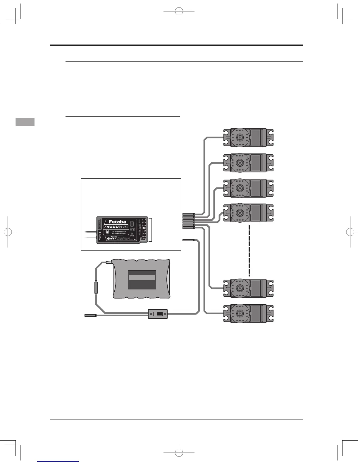
<Receiver and Servo Installation>
RECEIVER AND SERVO INSTALLATION
Receiver switch
Ni-Cd battery
Charging port
(CH1~8)
(B)
Servos
●Always connect the necessary number of servos.
●The receiver channel assignment depends on the
model type. See the Servo connection by model
type tables.
R6008HS (output connector section)
(Receiver connectors)
●B: Power supply
●CH1~8: Output connectors 1~8
●DATA port: (factory use only)
CH1~8,B
Receiver and servos connection diagram
Receiver and servos connection
Connect the receiver and servos in accordance with the connection diagram shown below. Always read
[Precautions when mounting the receiver and servos] or [Before using]. When mounting the receiver and
servos to the fuselage, connect the necessary points in accordance with the model's instruction manual.