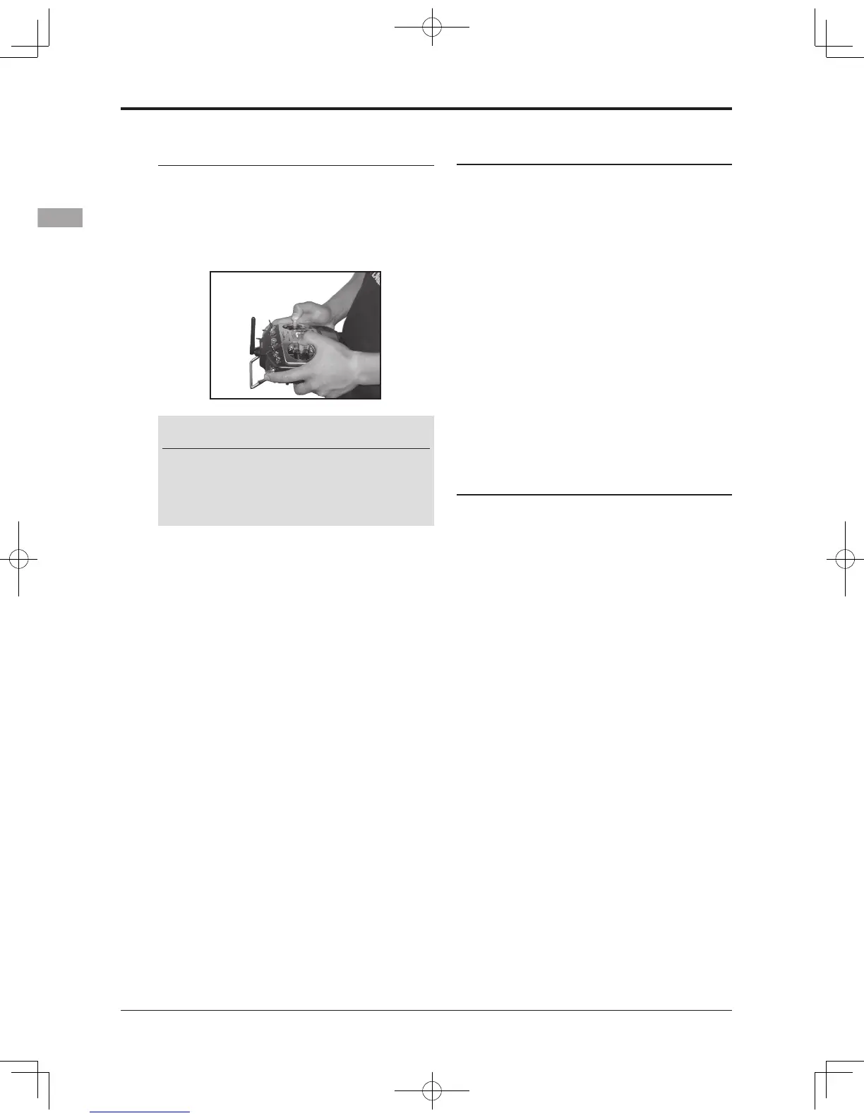
Transmitter's Antenna:
As with all radio frequency transmissions, the
strongest area of signal transmission is from the
sides of the transmitter's antenna. As such, the
antenna should not be pointed directly at the model.
If your flying style creates this situation, easily
move the antenna to correct this situation.
Monitor LED display
The status of the transmitter is displayed by LED
at the bottom left and right sides of the "T8FG"
logo.
LED (Left)
Displays the "non-default condition" warning.
• Blinking
P o we r sw i t c h i s t u r n e d on w h e n a n y
condition switch is activated (in the ON
state).
LED (Right)
D i s p l a y s t h e s t a t e o f r a d i o fr e q u e n c y
transmission.
• Off
Radio waves are in the OFF state.
• On
Radio waves are being transmitted.
Switch (SA-SH)
(Switch Type)
• SA : 3 positions; Alternate; Short lever
• SB : 3 positions; Alternate; Long lever
• SC : 3 positions; Alternate; Long lever
• SD : 3 positions; Alternate; Short lever
• SE : 3 positions; Alternate; Short lever
• SF : 2 positions; Alternate; Long lever
• SG : 3 positions; Alternate; Short lever
• SH : 2 positions; Momentary; Long lever
*You can choose switch and set the ON/OFF-direction in the
setting screen of the mixing functions.
CAUTION
Please do not grasp the transmitter's
antenna during ight.
Doing so may degrade the quality of the RF
transmission to the model.