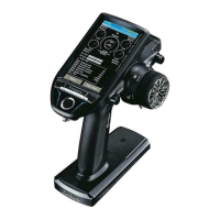
5. Throttle/Pitch curve setting
This function adjusts the throttle or pitch
operation curve in relation to the movement of the
throttle stick for each condition.
<Throttle curve setting example>
Activate the throttle curve of each condition with
the condition select switch.
●Normalcurveadjustment
Normal curve creates a basic throttle curve
centered near hovering. This curve is adjusted
together with the pitch curve (Normal) so that the
engine speed is constant and up/down control is
easiest.
●Idleupcurveadjustment
The low si de Th rottle curve creates a curv e
matched for aerobatics (loop, roll, 3D, etc.).
●Throttleholdcurveadjustment
The curve is not used when performing auto rotation
dives.
Conrmthattherateoftheslowestposition(0%)of
thestickis0%(initialsetting).
<Example of pitch curve setting>
Activate the pitch curve of each condition with
the condition select switch.
●Pitchcurve(Normal)
Make the pitch at hovering approximately +5
º
~6
º
.
Set the pitch at hovering with the stick position at
the50%pointasthestandard.
*Stability at hovering may be connected to the throttle curve.
Adjustment is easy by using the hovering throttle function
and hovering pitch function together.
●Pitchcurve(Idleup1)
The idle up 1 pitch curve function creates a curve
matchedtoairborneight.
Set to -7
º
~+12
º
as standard.
●Pitchcurve(Idleup2)
The high side pitch setting is less than idle up 1.
The standard is +8
º
.
●Pitchcurve(Hold)
At auto rotation, use the maximum pitch at both
the high and low sides.
[Pitch angle setting example]
Throttle hold: -7
º
~+12
º
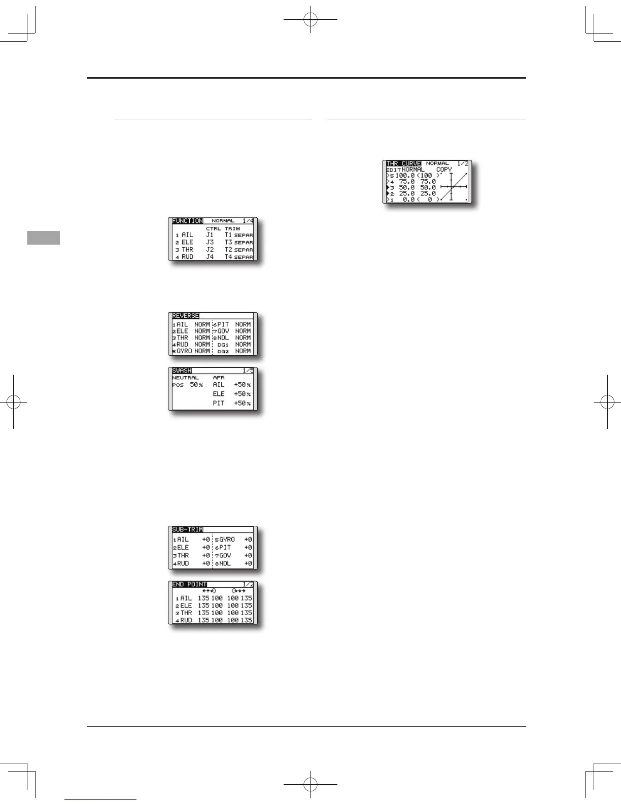
4. Servo Connection
Connect the throttle rudder, aileron, elevator,
pitch, and other servos in accordance with the
kit instruction manual. For a description of the
connection method, see "Receiver and Servos
Connection".
Note: The channel assigned to each function
can be checked at the Function menu of the
Linkage Menu.
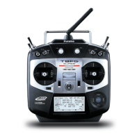
● If the direction of operation of the servo
is incorrect, use the Reverse function of
the Linkage Menu. Also use the swash AFR
function in other than the H-1 mode.
●Adjustthedirectionofoperationofthegyro.
(Gyro side function)
● Connect the throttle linkage so that the
carburetor can fully close at full trim throttle
cut.
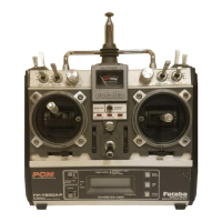
●Adjusttheneutralpositionatthelinkageside
andnetunewiththeSub-Trimfunctionand
End Point function. To protect the linkage,
a limit position can also be set with the End
Point function.
●Swashplatecorrection(ExceptH-1mode)
*If any interactions are noticed, for a description of the
linkage correction function, please refer to the SWASH
function, p.65.