Introduction
Invenia ABUS 2.0 – System Setup and Basic Service Manual 5-5
4700-0043-00 Rev. 4
General physical design of the ABUS 2.0 system
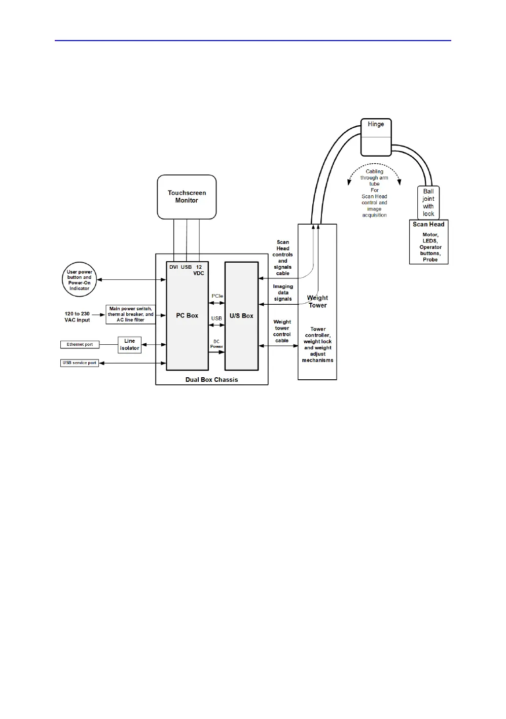
The following diagram is a high-level view of the major blocks in
the ABUS 2.0.
Figure 5-2. Invenia 2.0 block diagram
Physical / mechanical main elements
This section outlines the major pieces in the ABUS 2.0 system.
Major physical assemblies
The system's main physical elements are:
• Base (with casters, and fan filter)
• Dual Box Chassis (contains Ultrasound Box (providing front
end electronics and PC Box (providing back end
electronics))
• Service Table and covers
• Weight Tower (providing sliding Scan Arm, adjustable
compression pressure to Scan Head, support for operator

 Loading...