General theory of operation
Invenia ABUS 2.0 – System Setup and Basic Service Manual 5-11
4700-0043-00 Rev. 4
All fans and some board temperatures are monitored by system
software through the PC Box Motherboard and the data can be
viewed through the CSD (Common Service Desktop) on the
touchscreen monitor
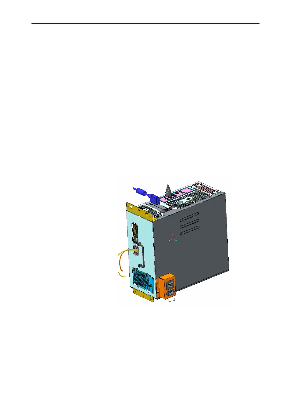
PC box
System control and digital computing functions are handled by
the components in this chassis.
The PC Box contains a computer motherboard with CPU, RAM,
solid state drive, and various support boards.
Mechanical design
The PC Box sits vertically, with air flow coming in from the
bottom. Air is pulled up through the box by fans at the top. The
box is removable as a single object; it is separate from the
Ultrasound Box.
Figure 5-6. CAD view of PC Box

 Loading...