Components and Functions (Theory)
5-12 Invenia ABUS 2.0 – System Setup and Basic Service Manual
4700-0043-00 Rev. 4
Major PC Box components and their functions and operation
The main items in the PC Box are:
Computing electronics in PC Box
Motherboard and CPU
Computing in the Invenia ABUS 2.0 is done in two places, the
PC Box and the Ultrasound Box. PC Box computing is done by
the Motherboard.
The ABUS is controlled by GE ABUS 2.0 application software
running on the PC under the Windows 7 Embedded operating
system.
GPU board
The GPU plugged into the Motherboard handles all graphics
processing.
The GPU provides a DVI output for the touchscreen monitor.
This GPU output connector is adjacent to the I/O Panel at the
top of the PC Box.
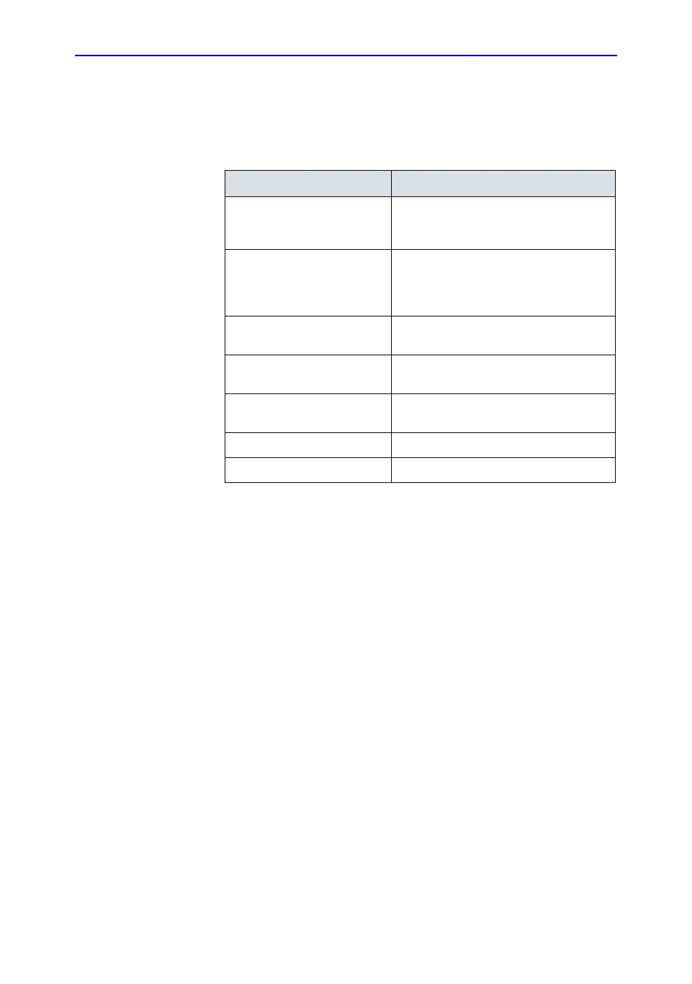
Table 5-2: PC Box components
Component Purpose
ACDC input box Handles AC line power input; has main
power switch with breaker and line filter.
Connects to ACDC Box
ACDC box Contains ACDC Power Supply feeding the
ATX Power Control board (PWA) that
distributes multiple voltage sources to the
system
Motherboard (Extended-ATX
form factor)
Has the CPU and provides various I/O
GPU (Graphics Processing
Unit) card
Performs all graphics handling for the
display
Solid State Drive data and
power interface board
Connects power and data to the SSD
Solid State Drive Provides mass data storage
Cooling fans Provide air flow from the PC Box to cool it

 Loading...