GE MEDICAL SYSTEMS
DIRECTION 2300000, REVISION 1 LOGIQ™ 5 SERVICE MANUAL
5 - 6 Section 5-4 - Front End
5-4-1 RLY
RLY ASSY contains of 3 phased array probe connectors and provides switchable connection between
probes and 64ch transmitters/receivers.
This board also has interface for a single CWD probe connector.
The main function of RLY ASSY is as follows.
- 3-to-1 selectors for three probes.
- Interface with JUSC bus (control bus)
- Interface with FEC ASSY for IIC bus.
- Interface with DCWD Connector.
- Supply/Cut control and failure detection of supply voltage for Mux circuit in a Probe.
- Device: Mechanical Relay
- Switch: 128ch 3:1 selector
- Temperature sensor in this assy detects temperature of RLY assy.
5-4-1-1 Interface to Probe
• Probe Status detection
- Detects whether or not a probe is connected.(POPEN)
- Detects ID code of a connected probe.(PCODE)
• Mux Interface
- Transfers control data of Mux to a probe.(CONSYS,CONSTA)
- Enables/Disables control of data.
- Detects whether Mux data setting is finished or not.
• Power Supply for Mux
- Supply/Cut control:
+5V and +15V on a connector are supplied while a probe is connected to the connector.
+/-SHV are supplied only while a probe is selected.
• Surface temperature
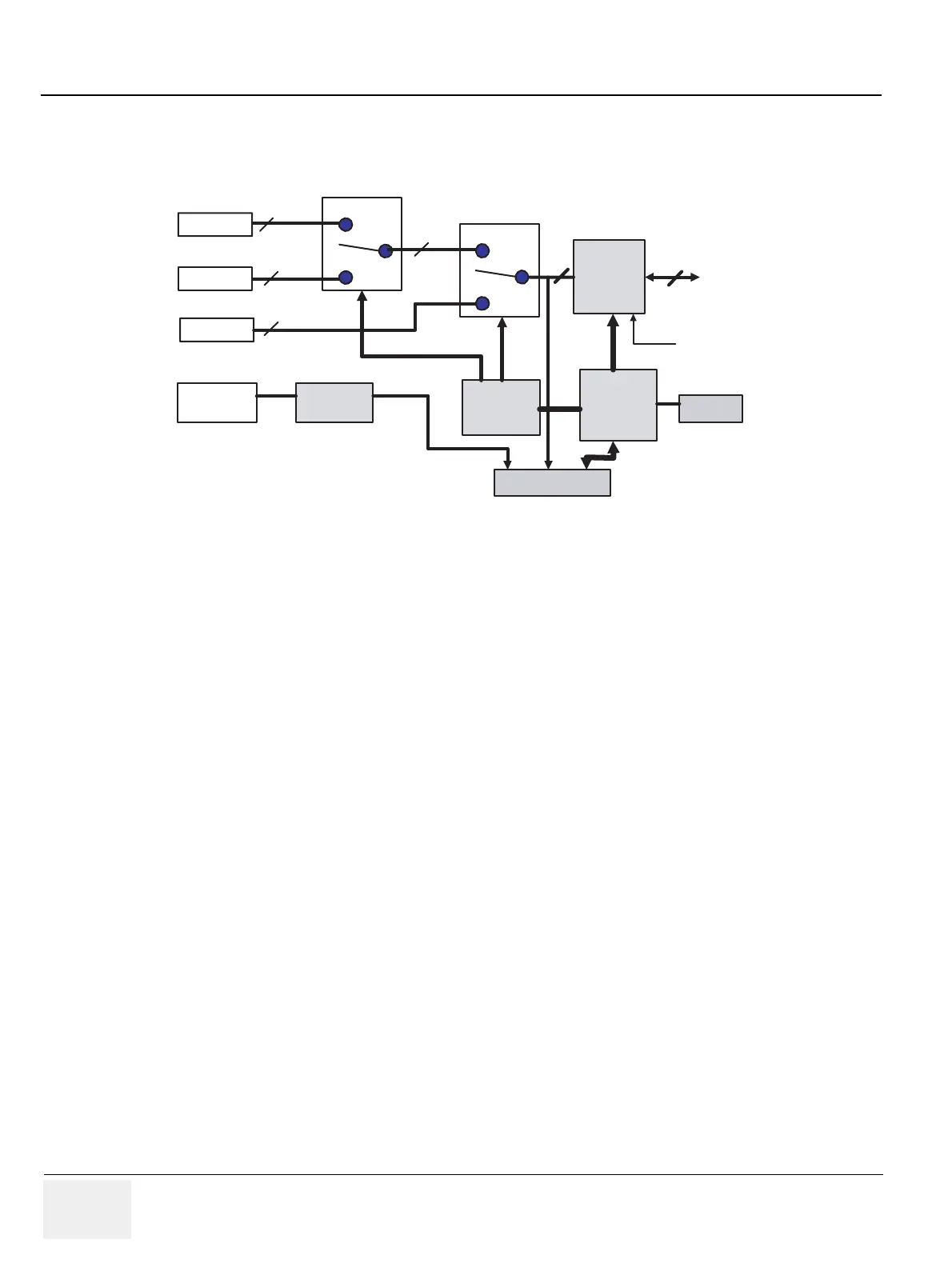
Figure 5-5 RLY Block Diagram
MUX
JUSC I/F
RLY Assy
RELAY
RELAY
128
Probe #1
Probe #2
Probe #1
128
1
28
1
28
128
64
Control
FPGA
To LM
Control
Circuit
Temperature
Sensor
DCWD
Probe I/F
Probe ID
I
/F
SHV
 Loading...


