GE MEDICAL SYSTEMS
D
IRECTION 2300000, REVISION 1 LOGIQ™ 5 SERVICE MANUAL
Chapter 5 Components and Functions 5 - 7
- Detects resistance of a thermistor in a probe head as voltage when the probe is
selected.(PTEMP) This signal is connected to FEC.
• LED Blinking
- The LED in a probe blinks when the probe is selected.
5-4-1-2 IIC bus
- Connects signals of IIC bus with a relay when IIC bus access is required.
- Selects one of thress probes that IIC access with 3-to-1 switch.
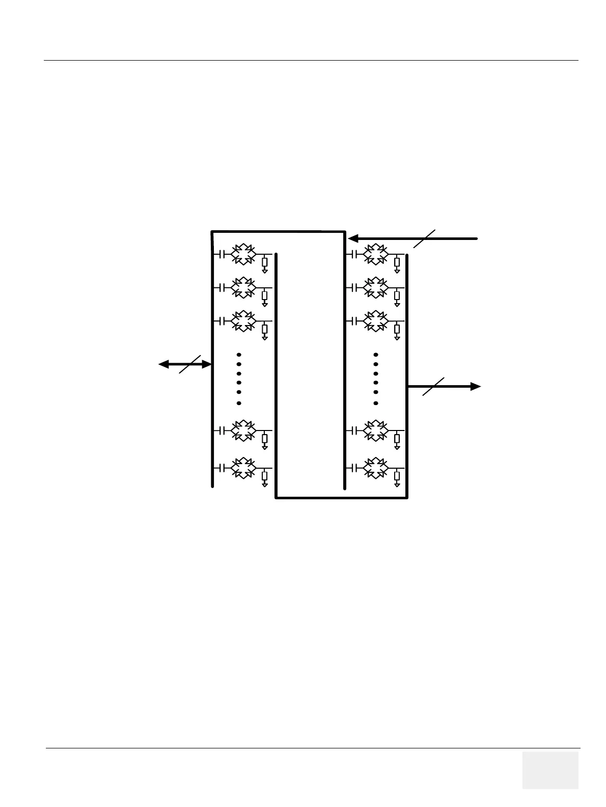
5-4-2 LMT
The main function of LMT ASSY is as follows.
- 64ch transmit/receiving switches protect a Pre-amp from a high voltage transmit pulse
- All control signal and DC power for RLY pass thorugh this LMT Assy
Figure 5-6 LMT Block Diagram
From RLY
To PMP
64
64
From ATD
64
 Loading...


