GE MEDICAL SYSTEMS
DIRECTION 2300000, REVISION 1 LOGIQ™ 5 SERVICE MANUAL
5 - 28 Section 5-8 - Power Diagrams
5-8-4 Rear Panel
5-8-4-1 Block Diagram
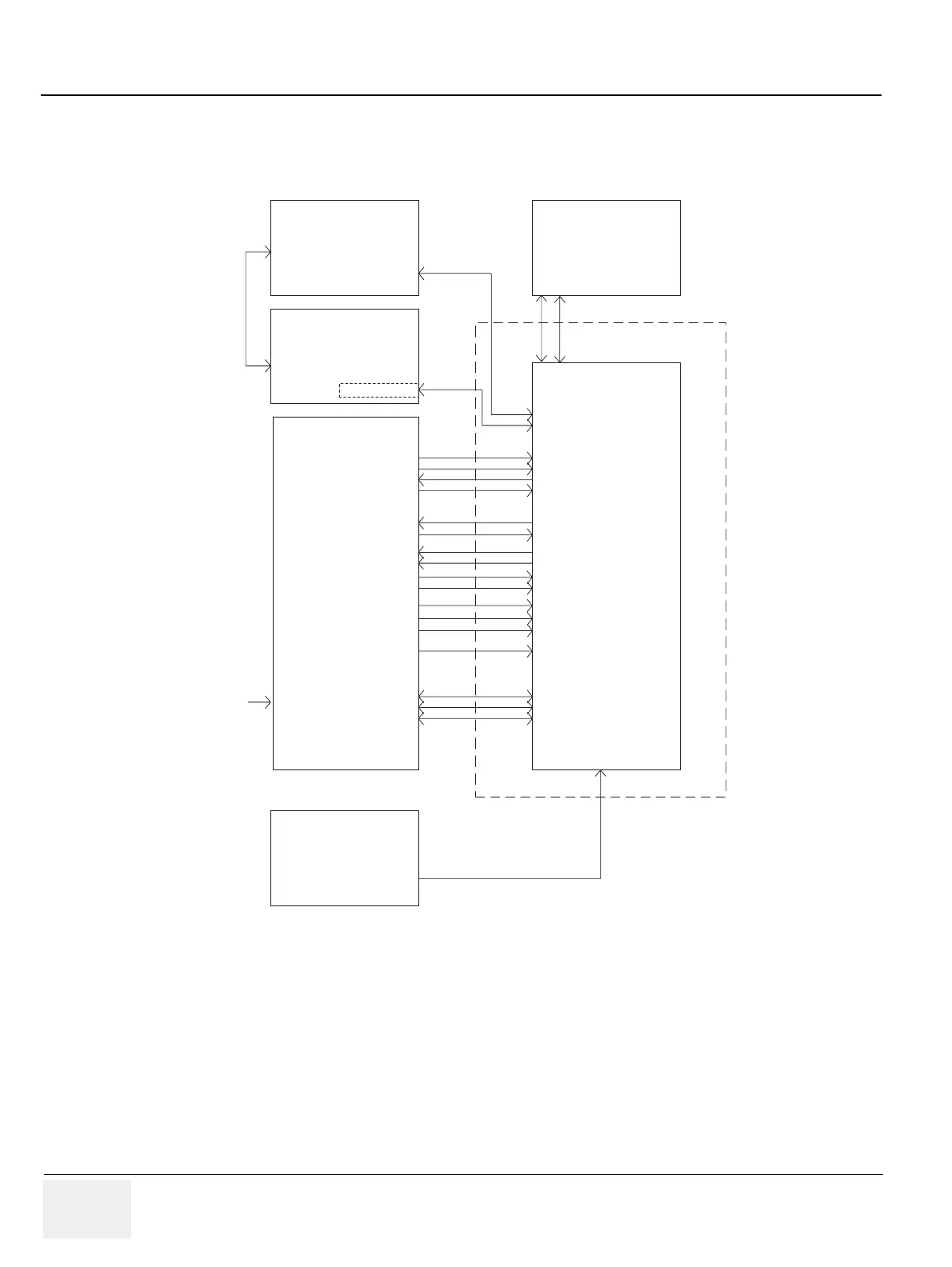
The REAR ASSY and REAR CONN 220V ASSY are the rear-panel assemblies which interconnect
external signals and power with the LOGIQ 5 system. Both of the assemblies are the same except the
circuit breaker’s current ratings depending on voltage of the system power source (See Safety
described below).
Figure 5-24 Rear Panel Block Diagram
VIC Board
Color PRN RGB OUT
Color PRN SYNC OUT
Color PRN COMP IN
VCR COMP IN
VCR COMP OUT
SHVS Y IN
SHVS C IN
SHVS Y OUT
SHVS C OUT
B/W PRN OUT
B/W Shutter OUT
Color PRN Shutter OUT
EXT VGA OUT
B/W Camera OUT
PC Mother
Board
Ethernet Card
RS-232 Port 0 ~ 4
EXT MODEM
COM 1
RS-232 Port
Line IN
KeyBoard Assy
USB
Foot Switch
Rear Panel
Color PRN RGB OUT
Color PRN SYNC OUT
Color PRN COMP IN
VCR COMP IN
VCR COMP OUT
SHVS Y IN
SHVS C IN
SHVS Y OUT
SHVS C OUT
B/W PRN OUT
B/W Shutter OUT
Color PRN Shutter OUT
EXT VGA OUT
B/W Camera OUT
Ethernet Port
Insite
USB
Foot
Switch
Remote 1
Remote 2
Service
Remote 1
Remote 2
Service
From
PC2IP Board
Power Box Assy
OUTLET
AC Power
OUTLET
 Loading...


