GE MEDICAL SYSTEMS
D
IRECTION 2300000, REVISION 1 LOGIQ™ 5 SERVICE MANUAL
Chapter 7 Diagnostics/Troubleshooting 7 - 13
• Cable to RDi board in Rear Panel and Keyboard for Power switch.
• Connect J4 connector in RDi board with CON4 connector in keyboard.
• Cable to RDi assy to AC Power Assy. - Connect J6 connector in RDi board with CON1 connector
in AC Power Assy.
• Cable to RDi board to BEP assy. - Connect J5 connector to CON17 connector in BEP.
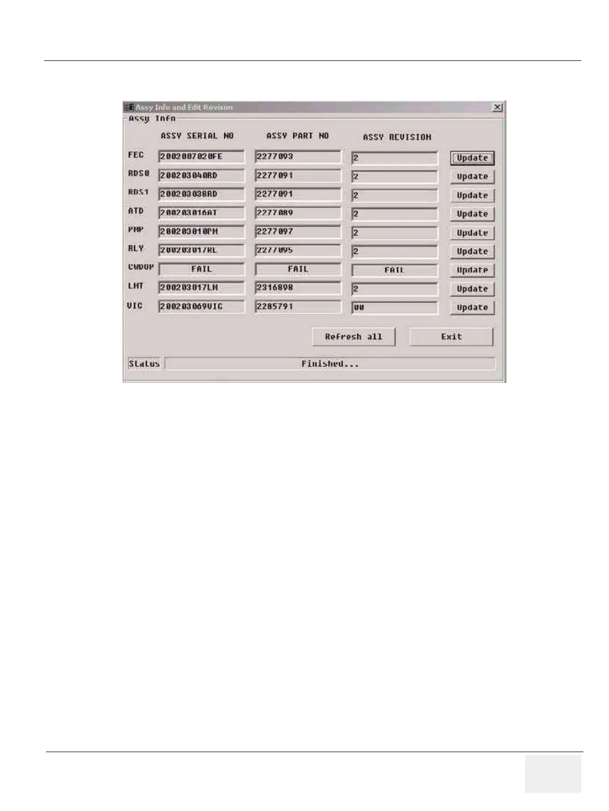
Figure 7-8 Diagnostic Group Selections - SCB Tests
 Loading...


