GE MEDICAL SYSTEMS
DIRECTION 2300000, REVISION 2 LOGIQ™5 SERVICE MANUAL
8-90 Section 8-7 - PCB Boards
8-7-1-4 Removal Procedure (cont’d)
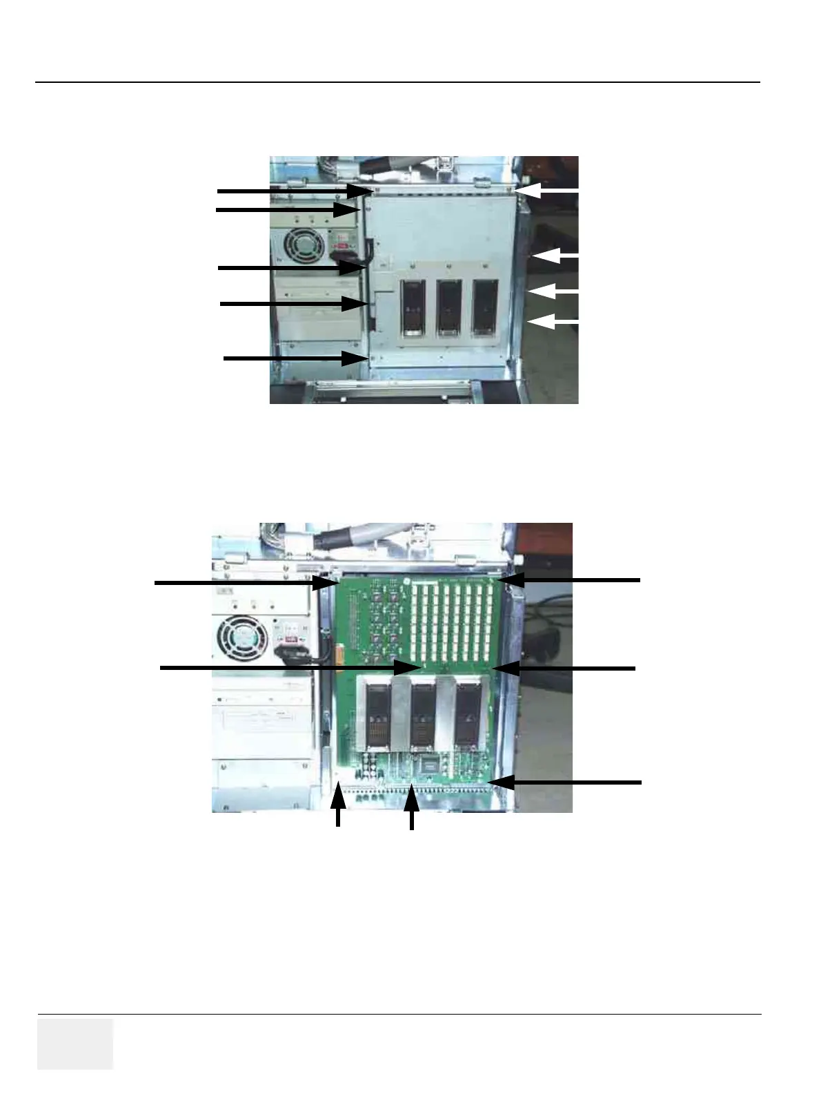
4.) Unscrew nine (9) screws (6-14) to remove the RLY Board Cover. Refer to Figure 8-89.
NOTE: Bind head screw is used at the location number (8).
5.) Unscrew seven (7) screws (15-21) to remove the RLY Board. Refer to Figure 8-90.
6.) Get the probe connector and pull the RLY board Out.
Figure 8-89 Removing the RLY board Cover
Figure 8-90 Unscrew 7 screws to remove the RLY Board
(7)
(8)
(9)
(10)
(11)
(12)
(13)
(14)
(6)
Probe Connector
(15)
(16)
(17)
(18)
(19)
(20)
(21)
 Loading...


