GE MEDICAL SYSTEMS
D
IRECTION 2300000, REVISION 2 LOGIQ™5 SERVICE MANUAL
Chapter 8 Replacement Procedures 8-141
8-8-2-4-2 Removal of VIC board
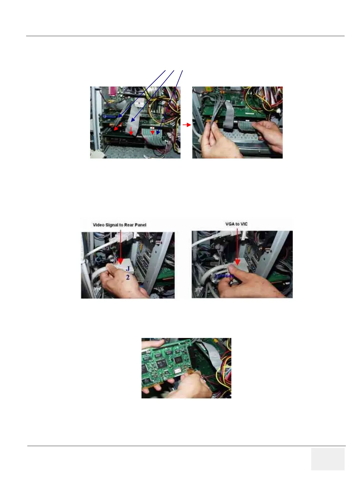
1.) Disconnect all of connect in VIC assy. Refer to Figure 8-161.
2.) 5 connectors inside BEP. 14 pins connector to chassi from VIC. 50pin half pitch flat cable connector.
50pin flat cable connector to PC2IP card. 2 pin connector to motherboard for power control. 3 pin
connector to motherboard for LED.
3.) Disconnect 2 connectors outside of BEP.
4.) Disconnect 2 connectors from motherboard.
Figure 8-161 Connectors on VIC assy
Figure 8-162 Video signal to Rear Panel & VGA to VIC
Figure 8-163 Disconnect 2 connectors
J8 ,
J12
J8 ,
J12