GE MEDICAL SYSTEMS
DIRECTION 2300000, REVISION 2 LOGIQ™5 SERVICE MANUAL
8-146 Section 8-8 - PC Block
8-8-3-4 Removal Procedure (cont’d)
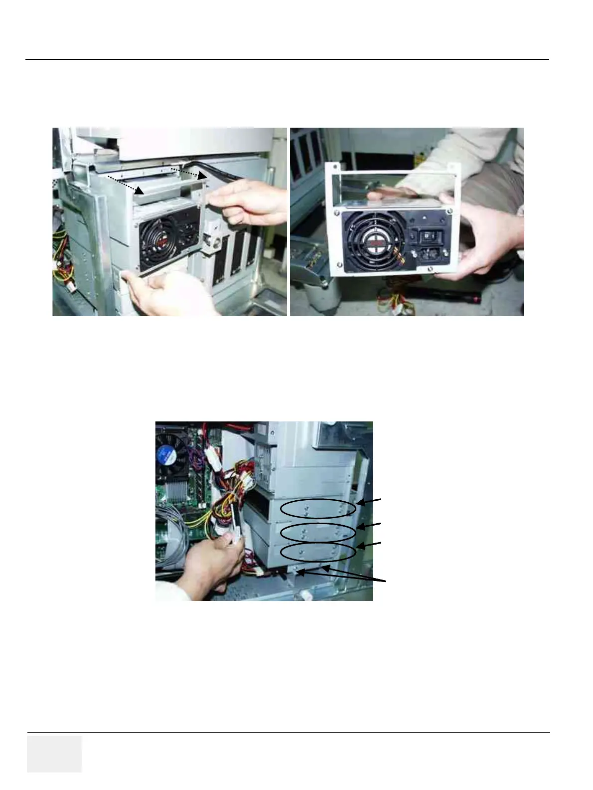
5.) Unscrew 2 screws on theATX power bracket.
6.) Take out the ATX smps.
7.) To remove Hard disk and CDRW Unplug the IDE cable for HDD or CDRW drive and power
connector.
8.) Unscrew the screws on the chassi for fixture.
9.) Take out CDRW or Hard disk.
Figure 8-171 Take out the ATX SMPS
Figure 8-172 Screws for Peripheral in BEP
1
2
1
2
1
2
3
4
1
2
3
4
4 screws for
CDRW
4 screws for
MOD
4 screws for
Patient IO
2 screws for
Hard Disk
4 screws for
CDRW
4 screws for
CDRW
4 screws for
MOD
4 screws for
Patient IO
4 screws for
MOD
4 screws for
MOD
4 screws for
Patient IO
4 screws for
Patient IO
2 screws for
Hard Disk
2 screws for
Hard Disk