GE MEDICAL SYSTEMS
DIRECTION 2300000, REVISION 2 LOGIQ™5 SERVICE MANUAL
8-164 Section 8-9 - Power Block
8-9-5-4 Removal Procedure (cont’d)
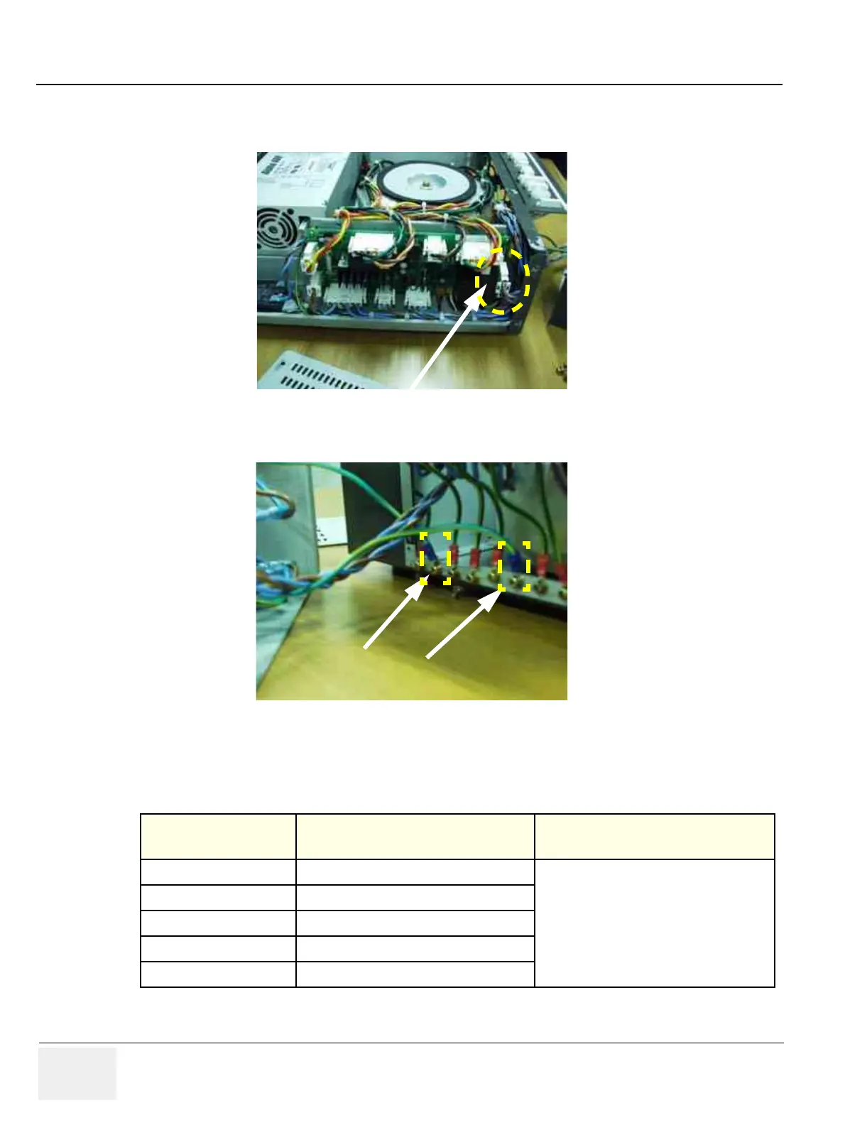
3.) Disconnect one (1) connector (J1) from the JPC Assy. Refer to Figure 8-194.
4.) Unscrew two (2) ground screws (7-8). Refer to Figure 8-195.
5.) Remove the AC Power Box.
6.) Perform the following functional tests. If all are successful, include the debrief script provided below.
8-9-5-5 Mounting Procedure
Install the new parts in the reverse order of removal.
Figure 8-194 Disconnect 1 connector
Figure 8-195 Unscrew two ground screws
Table 8-54 Functional Tests
Service Manual
Section
Functional Test / Diagnostic Test Debrief Script
Section 4-3-1
Power On/Boot Up
“Service Manual, Direction
2300000, Rev 1+, Section 8-9-5. Equipment
passed all required tests and is ready for use. “
Section 4-3-2
Power Off / Shutdown
Section 4-9-19
AC Power Box function check procedure
Section 4-3-4
System B/M-Mode Checks
Section 4-3-5
System CFM and PWD Checks
J1
(7)
(8)
AC POWER BOX VIEW
 Loading...


