GE MEDICAL SYSTEMS
DIRECTION 2300000, REVISION 1 LOGIQ™ 5 SERVICE MANUAL
3 - 20 Section 3-2 - Installation Reminders
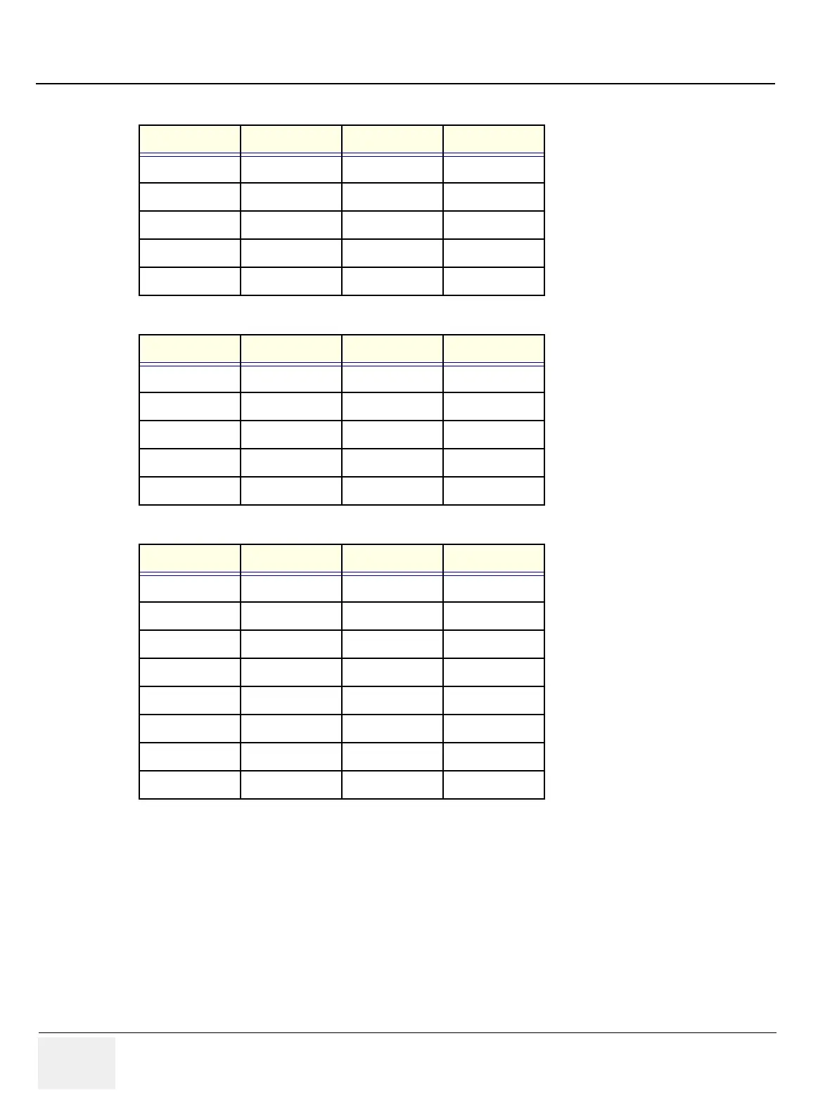
3-6-4-1 External I/O Pin Outs
Pin No. Signal Pin No. Signal
1N/A6DSR
2RXD7RTS
3TXD8GTS
4DTR9 N/A
5GND
Table 3-6 Pin Assignments of RS232C for Remote 1 and Remote 2
Pin No. Signal Pin No. Signal
1NC6NC
2RXD7 NC
3TXD8 NC
4NC9 RI
5GND
Table 3-7 Pin Assignments of RS232C for Service
Pin No. Signal Pin No. Signal
1RED9 N/A
2 GREEN 10 SGND
3BLUE11 N/A
4N/A12N/A
5 GND 13 HSYNC
6 RGND 14 VSYNC
7GGND15 N/A
8BGND
Table 3-8 Pin Assignments of DB15 connector for External VGA