GE MEDICAL SYSTEMS
D
IRECTION 2300000, REVISION 1 LOGIQ™ 5 SERVICE MANUAL
Chapter 3 Installation 3 - 21
3-6-4-1 External I/O Pin Outs (cont’d)
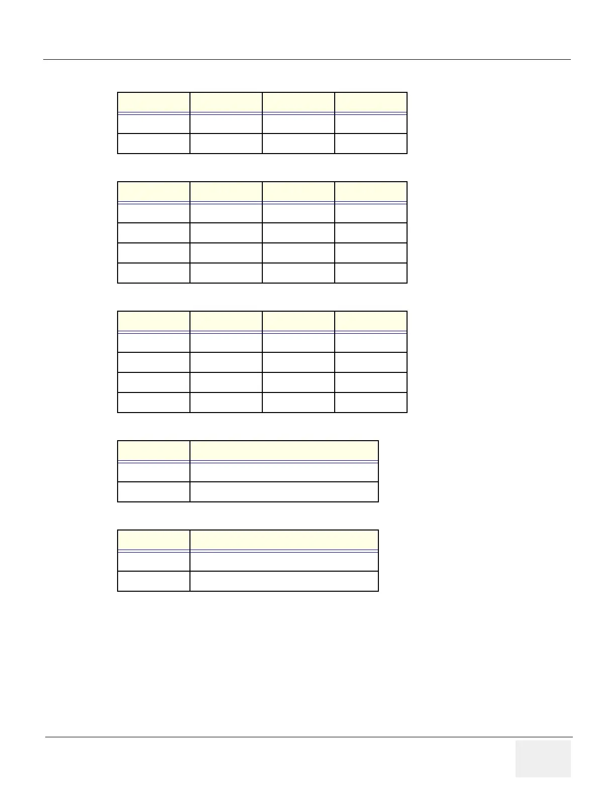
Pin No. Signal Pin No. Signal
1+5 VDC3DATA +
2 DATA - 4 GND
Table 3-9 Pin Assignments of USB
Pin No. Signal Pin No. Signal
1TX+5 NC
2 TX- 6 RX-
3RX+7 NC
4NC8NC
Table 3-10 Pin Assignments of InSite - RJ45 Male Connector
Pin No. Signal Pin No. Signal
1TX+5 NC
2 TX- 6 RX-
3RX+7 NC
4NC8NC
Table 3-11 Pin Assignments of Ethernet
Pin No. Output Signal
1 PRINT*1
2 Signal GND
Table 3-12 Pin Assignment of Mini-Jack for Controlling B/W Printer
Pin No. Output Signal
1 SHUTTER*2
2 Signal GND
Table 3-13 Pin Assignment of Mini-Jack for Controlling Color