4-54 PQM Power Quality Meter GE Power Management
4.6 S5 TESTING 4 PROGRAMMING
4
4.6 S5 TESTING 4.6.1 TEST OUTPUT RELAYS & LEDS
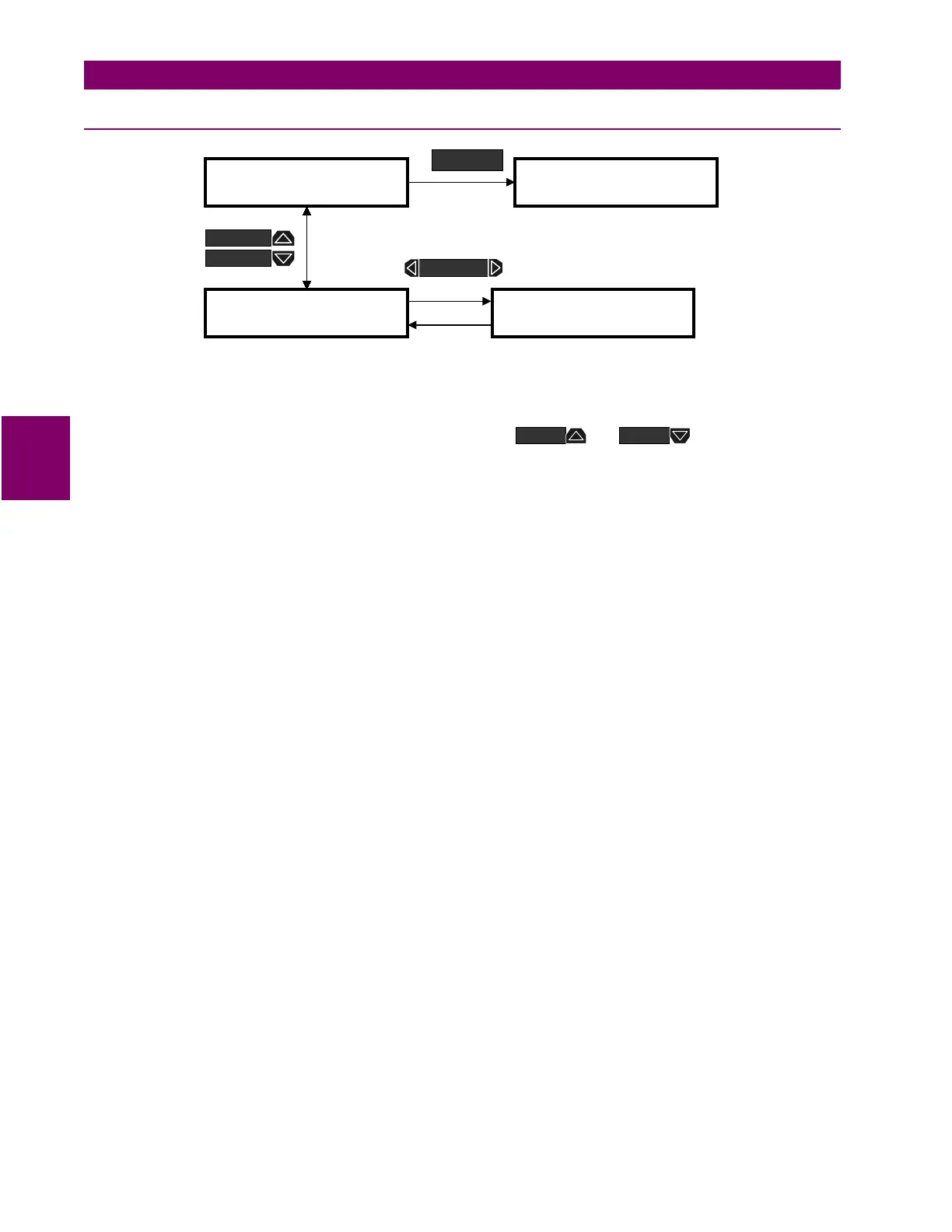
Figure 4–34: SETPOINTS PAGE 5 – TESTING
•
OPERATION TEST
: To verify correct operation of output relay wiring, each output relay and status indica-
tor can be manually forced on or off via the keypad or serial port.
While the
OPERATION TEST
setpoint is displayed, use the or keys to scroll to the
desired output relay and/or status indicator to be tested. As long as the test message remains displayed
the respective output relay and/or status indicator will be forced to remain energized. As soon as a new
message is selected, the respective output relay and/or status indicator return to normal operation.
]] SETPOINTS
]] S5 TESTING
] TEST RELAYS & LEDS
]
OPERATION TEST:
NORMAL MODE
]] SETPOINTS
]] S1 PQM SETUP
SETPOINT
MESSAGE
MESSAGE
MESSAGE
VALUE

 Loading...


