GE Power Management PQM Power Quality Meter 7-63
7 MODBUS COMMUNICATIONS 7.3 MODBUS MEMORY MAP
7
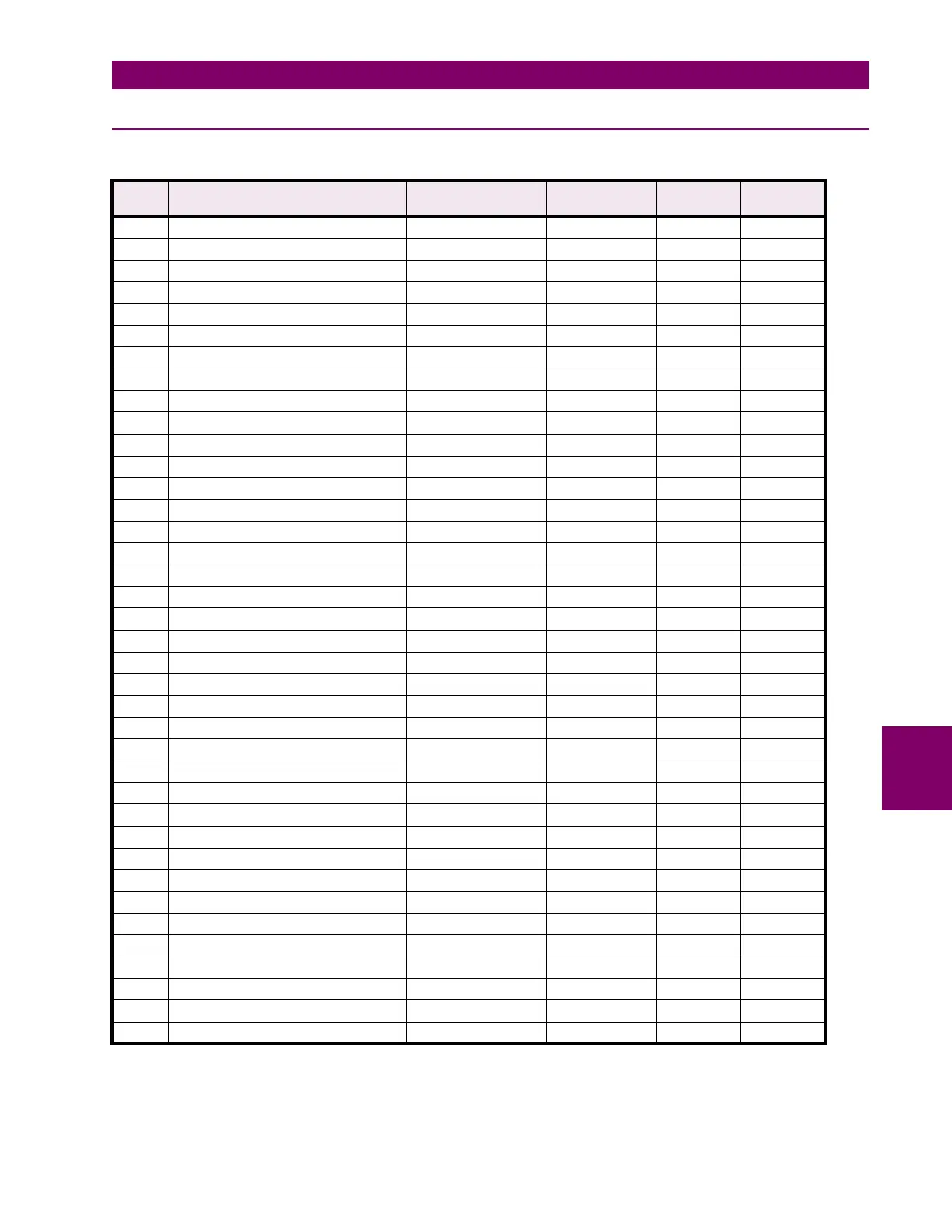
7.3.5 ANALOG OUTPUT PARAMETER RANGE
Table 7–12: ANALOG OUTPUT PARAMETER RANGE FOR SERIAL PORTS (Sheet 1 of 2)
NO. ANALOG OUT PARAMETER RANGE STEP UNITS/
SCALE
DEFAULT
0 Not Used 0 0 --- 0
1 Phase A Current 0 to 150 1 % 0
2 Phase B Current 0 to 150 1 % 0
3 Phase C Current 0 to 150 1 % 0
4 Neutral Current 0 to 150 1 % 0
5 Average Phase Current 0 to 150 1 % 0
6 Current Unbalance 0 to 1000 1 0.1 x% 0
7 Voltage Van 0 to 200 1 % 0
8 Voltage Vbn 0 to 200 1 % 0
9 Voltage Vcn 0 to 200 1 % 0
10 Voltage Vab 0 to 200 1 % 0
11 Voltage Vbc 0 to 200 1 % 0
12 Voltage Vca 0 to 200 1 % 0
13 Average Phase Voltage 0 to 200 1 % 0
14 Average Line Voltage 0 to 200 1 % 0
15 Voltage Unbalance 0 to 1000 1 0.1 x% 0
16 Frequency 0 to 7500 1 0.01 xHz 0
17 *3 Phase PF –99 to +99 1 0.01 xPF 0
18 3 Phase kW –32500 to +32500 1 kW 0
19 3 Phase kvar –32500 to +32500 1 kvar 0
20 3 Phase kVA 0 to 65400 1 kVA 0
21 3 Phase MW –32500 to +32500 1 0.1 xMW 0
22 3 Phase Mvar –32500 to +32500 1 0.1 xMvar 0
23 3 Phase MVA 0 to 65400 1 0.1 xMVA 0
24 *Phase A PF –99 to +99 1 0.01 xPF 0
25 Phase A kW –32500 to +32500 1 kW 0
26 Phase A kvar –32500 to +32500 1 kvar 0
27 Phase A kVA 0 to 65400 1 kVA 0
28 *Phase B PF –99 to +99 1 0.01 xPF 0
29 Phase B kW –32500 to +32500 1 kW 0
30 Phase B kvar –32500 to +32500 1 kvar 0
31 Phase B kVA 0 to 65400 1 kVA 0
32 *Phase C PF –99 to +99 1 0.01 xPF 0
33 Phase C kW –32500 to +32500 1 kW 0
34 Phase C kvar –32500 to +32500 1 kvar 0
35 Phase C kVA 0 to 65400 1 kVA 0
36 3 Phase +kWh Used 0 to 65400 1 kWh 0
37 3 Phase +kvarh Used 0 to 65400 1 kvarh 0
*
Due to the fact that –0 and +0 both exist for power factor, the value stored in the PQM serial register is the
opposite of the value shown on the display.
Example: If the range 0.23 lead (–0.23) to 0.35 lag (+0.35) is required, –77 (–100+23)and +65 (100–35) must
be sent.

 Loading...


