GE Power Management PQM Power Quality Meter 2-15
2 INSTALLATION 2.2 ELECTRICAL
2
2.2.6 SWITCH INPUTS (OPTIONAL)
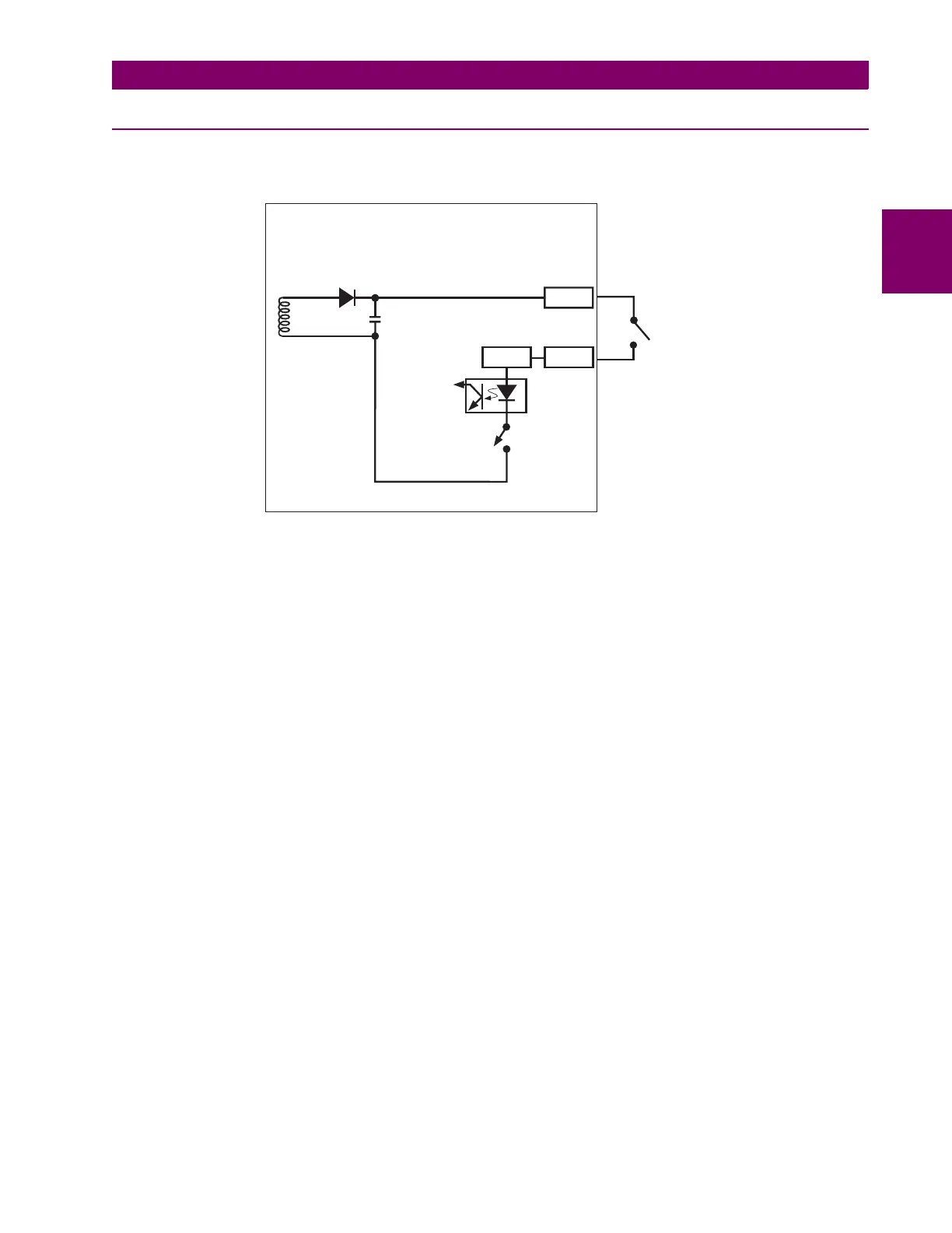
The PQM has four programmable switch inputs that can be used for numerous functions. The figure below
shows the internal circuitry of the switches.
Figure 2–11: SWITCH INPUT CIRCUIT
Each switch input can be programmed with a 20-character user defined name and can be selected to accept a
normally open or normally closed switch. A list various functions that are assignable to switches is shown
below, followed by a description of each function.
•
ALARM RELAY:
When a switch input is assigned to the alarm relay, a change in the switch status pro-
duces an alarm condition and the alarm relay activates.
•
PULSE INPUT 1 / 2 / 3 / 4:
When a switch input is assigned as a pulse input counter, the PQM counts the
number of transitions from open to closed when the input is configured as normally open and closed to
open when the input is configured as normally closed. The minimum pulse width required for the PQM to
read the switch is 150 ms. Therefore, for the PQM to read one pulse, the switch input must be in its inac-
tive state (closed/open) for a minimum of 150 ms then in its active state (open/closed) for another 150 ms.
See Section 1.3: SPECIFICATIONS on page 1–11 for more details.
•
NEW DEMAND PERIOD:
The PQM can be used for load shedding by assigning a switch input to a new
demand period. This allows the PQM demand period to be synchronized with the utility meter. One of the
billing parameters used by a utility is peak demand. By synchronizing the PQM to the utility meter, the
PQM can monitor the demand level read by the utility meter and perform load shedding to prevent the
demand from reaching the penalty level. The utility meter provides a dry contact output which can be con-
nected to one of the PQM switch inputs. When the PQM senses a contact closure, it starts a new demand
period (with Block Interval Demand calculation only).
•
SETPOINT ACCESS:
The access terminals must be shorted together in order for the faceplate keypad to
have the ability to store new setpoints. Typically the access terminals are connected to a security key-
switch to allow authorized access only. Serial port commands to store new setpoints operate even if the
OFF ALARM RELAY NEW DEMAND PERIOD
SETPOINT ACCESS SELECT ANALOG OUTPUT SELECT ANALOG INPUT
AUX1 RELAY AUX2 RELAY AUX3 RELAY
PULSE INPUT 1 PULSE INPUT 2 PULSE INPUT 3
PULSE INPUT 4 CLEAR ENERGY CLEAR DEMAND
EXTERNAL
SWITCH
OPTO
ISOLATION
TYPICAL
SWITCH
TERMINALS
ISOLATED
POWER
SUPPLY
+24VDC
PQM
TO LOGIC
10mA
PULSED
FILTER IN
COM

 Loading...


