5-6 PQM Power Quality Meter GE Power Management
5.2 A1 METERING 5 MONITORING
5
5.2.3 PHASORS
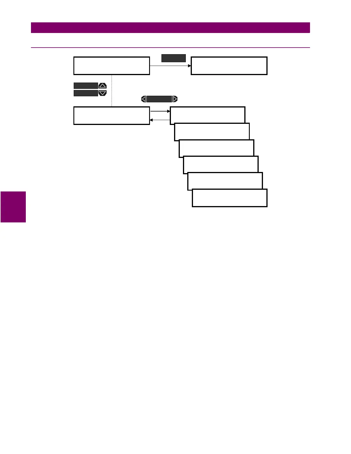
Figure 5–4: ACTUAL VALUES PAGE 1 – METERING/PHASORS
Va PHASOR
: Displays a phasor representation for the magnitude and angle of Va. Va is used as a reference
for all other phasor angles. If there is no voltage present at the PQM voltage inputs, then Ia will be used as the
reference for all other angles. Va is also used as the reference when in Simulation Mode.
Vb PHASOR
: Displays a phasor representation for the magnitude and angle of Vb. Vb uses the angle of Va as
a reference point. If there is no voltage at the PQM voltage inputs, Ia is used as the reference. Vb is not dis-
played when the PQM is configured for the 3 WIRE DELTA/2 VTs, 4 WIRE WYE/2 VTs, or SINGLE PHASE
DIRECT connections.
Vc PHASOR
: A phasor representation for the magnitude and angle of Vc is displayed here. Vc uses the angle
of Va as a reference point. If there is no voltage at the PQM voltage inputs, Ia is used as the reference. Vc is
not displayed when the PQM is configured for SINGLE PHASE DIRECT connection.
Ia PHASOR
: A phasor representation for the magnitude and angle of Ia is displayed here. Ia is used as a refer-
ence for all other Phasor angles only when there is no voltage present at the PQM voltage inputs, otherwise,
Va is used as the reference.
Ib PHASOR
: A phasor representation for the magnitude and angle of Ib is displayed here. Ib uses the angle of
Va as a reference point. If there is no voltage at the PQM voltage inputs, Ia is used as the reference. Ib is not
displayed when the PQM is configured for SINGLE PHASE DIRECT connection.
Ic PHASOR
: A phasor representation for the magnitude and angle of Ic is displayed here. Ic is uses the angle
of Va as a reference point. If there is no voltage at the PQM voltage inputs, Ia is used as the reference. Ic is not
displayed when the PQM is configured for SINGLE PHASE DIRECT connection.
]] ACTUAL VALUES
]] A1 METERING
] PHASORS
]
Va PHASOR
0V 0° LAG
Vb PHASOR
0V 0° LAG
Vc PHASOR
0V 0° LAG
Ia PHASOR
0A 0° LAG
]] ACTUAL VALUES
]] A2 STATUS
ACTUAL
Ib PHASOR
0A 0° LAG
Ic PHASOR
0A 0° LAG
MESSAGE
MESSAGE
MESSAGE

 Loading...


