GE Power Management PQM Power Quality Meter A-19
APPENDIX A A.1 PQM APPLICATION NOTES
A
A.1.9 PULSE TOTALIZER APPLICATION
APPLICATION NOTE PQMAN10: PULSE INPUT APPLICATION FOR USE AS A PULSE TOTALIZER
The PQM has up to 4 Logical Switch Inputs that can be configured as Pulse Input Counters. One common
application of these Pulse Inputs is their use as an energy totalizer for more than one circuit. One PQM can
totalize input from up to 4 different sources and sum these results into a single register. Variables to consider
when using the PQM as a Pulse Input Counter are:
• PQM Switch Input A/B/C/D Function
• PQM Switch Input A/B/C/D Activation
• PQM Switch Input A/B/C/D Name
• PQM Pulse Input (Units)
• PQM Pulse Input A/B/C/D (Value)
• PQM Totalized Pulse Input
1. PQM Switch Input A/B/C/D Function: This parameter defines the functionality to be provided by the PQM
Switch Input. For use as a Pulse Input Counter, the PQM Switch Input to be used must be assigned as
either Pulse Input 1/2/3 or 4.
2. PQM Switch Input A/B/C/D Activation: This parameter is set to OPEN or CLOSED. The PQM will see the
operation of the Switch Input in the state as defined by this parameter.
3. PQM Switch Input A/B/C/D Name: This parameter defines the name given to each of the Switch Inputs
used. It is used as a label only and has no bearing on the operation of the Switch Input.
4. PQM Pulse Input (Units): This parameter is the name given to the base units that the PQM Pulse Input(s)
will be counting. It is used as a label only and has no bearing on the operation of the Pulse Input.
5. PQM Pulse Input A/B/C/D Value: This is the value assigned to each counting operation as determined by
the Switch Input.
6. PQM Totalized Pulse Input: This parameter creates a summing register of the various Pulse Inputs config-
ured. It can be configured for any combination of the PQM Switch Inputs used as Pulse Inputs.
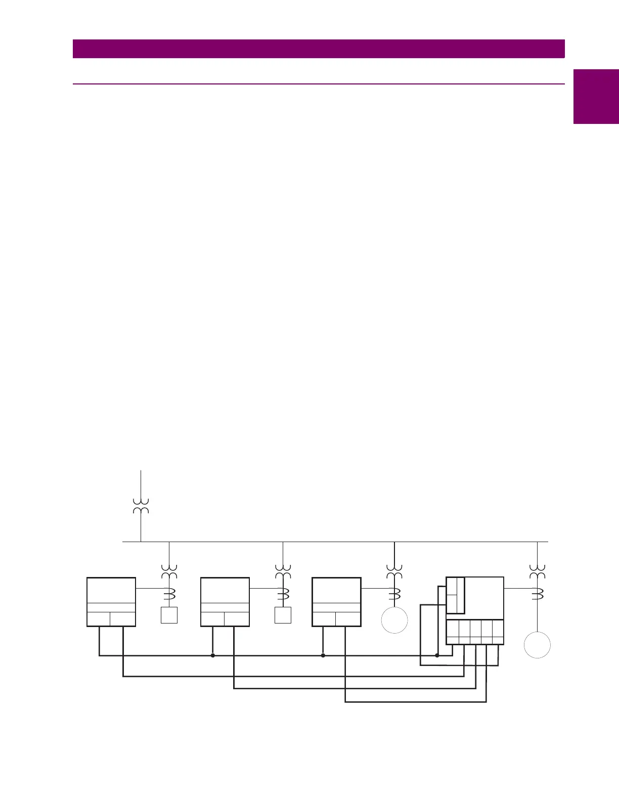
Configuring the PQM to Totalize Energy From Multiple Metering Locations:
Figure A–3: MULTIPLE METERING LOCATIONS
M
LL
PQM
#1
PQM
#2
PQM
#3
F1 F2 F3
M
F4
AUX1 AUX1 AUX1
COM COM COM
41 41 4142 42 42
N/O N/O N/O
AUX1
COM
41 42
N/O
PQM
#4
+24VDC
SW1
SW2
SW3
SW4
33 32 31 30 29

 Loading...


