7-8 PQM Power Quality Meter GE Power Management
7.2 MODBUS FUNCTIONS 7 MODBUS COMMUNICATIONS
7
7.2.6 FUNCTION CODE 07 – READ DEVICE STATUS
Modbus Implementation
: Read Exception Status
PQM Implementation
: Read Device Status
This is a function used to quickly read the status of a selected device. A short message length allows for rapid
reading of status. The status byte returned will have individual bits set to 1 or 0 depending on the status of the
slave device.
PQM General Status Byte:
LSBit B0: Alarm condition = 1
B1: Self test failure = 1
B2: Alarm relay energized = 1
B3: Aux 1 relay energized = 1
B4: Aux 2 relay energized = 1
B5: Aux 3 relay energized = 1
B6: Not used
MSBit B7: Not used
MESSAGE FORMAT AND EXAMPLE:
Request status from slave 11.
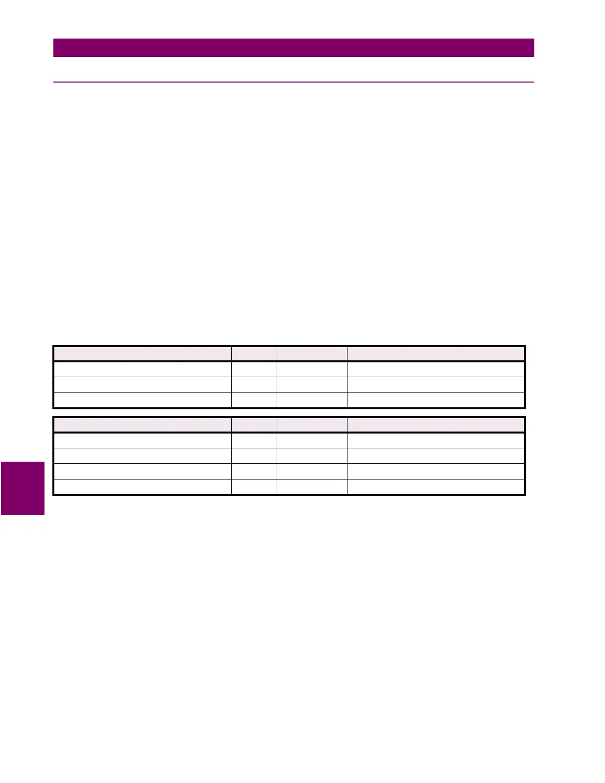
Table 7–5: MASTER/SLAVE PACKET FORMAT FOR FUNCTION CODE 07H
MASTER TRANSMISSION BYTES EXAMPLE DESCRIPTION
SLAVE ADDRESS 1 11 message for slave 17
FUNCTION CODE 1 07 read device status
CRC 2 4C 22 CRC error code
SLAVE RESPONSE BYTES EXAMPLE DESCRIPTION
SLAVE ADDRESS 1 11 message from slave 17
FUNCTION CODE 1 07 read device status
DEVICE STATUS (see definition above) 1 2C status = 00101100 (in binary)
CRC 2 22 28 CRC error code

 Loading...


