5-24 PQM Power Quality Meter GE Power Management
5.4 A3 POWER ANALYSIS 5 MONITORING
5
5.4 A3 POWER ANALYSIS 5.4.1 POWER QUALITY
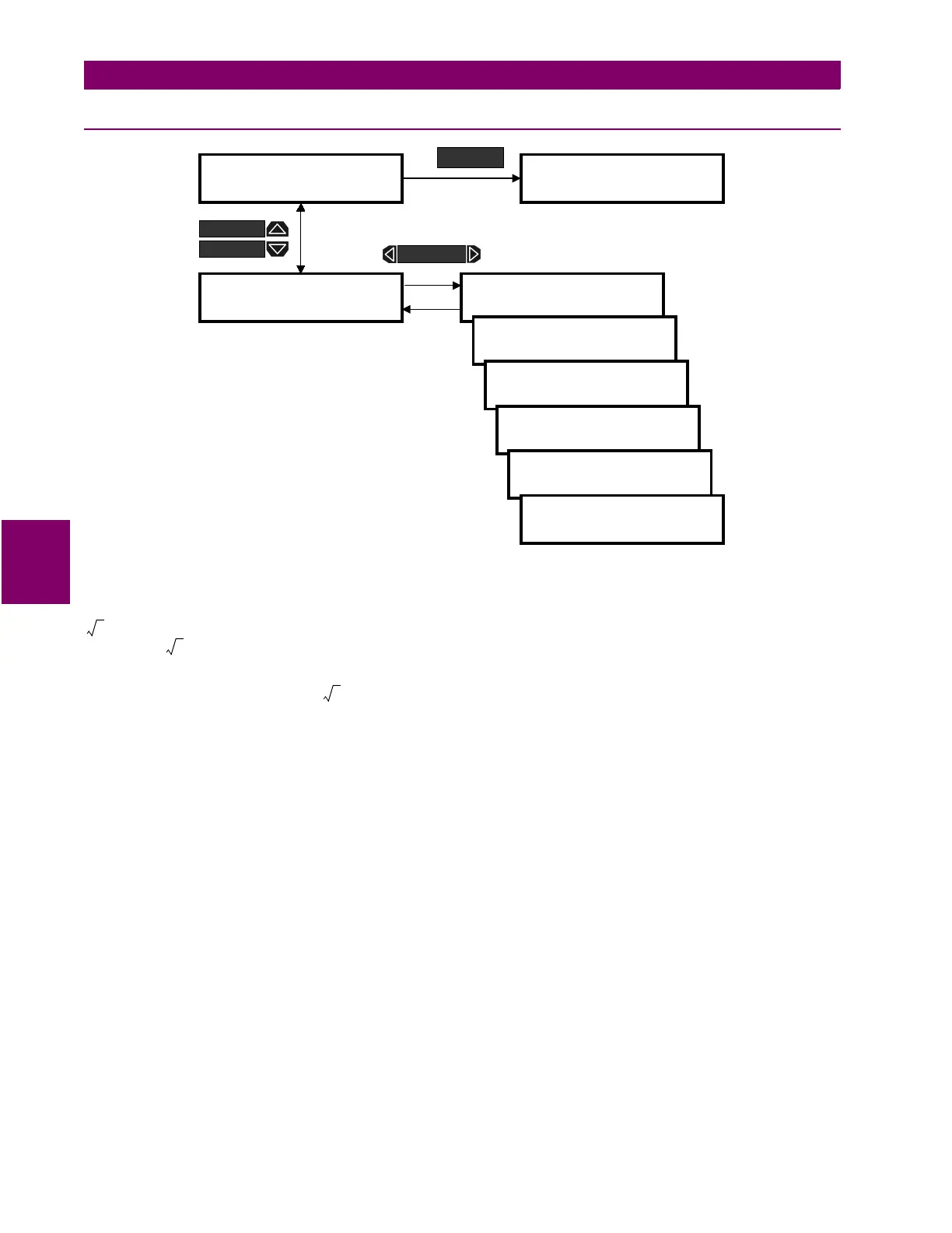
Figure 5–17: ACTUAL VALUES PAGE 3 – POWER QUALITY VALUES
Ia / Ib / Ic CREST FACTOR:
The crest factor describes how much the load current can vary from a pure sine
wave while maintaining the system’s full rating. A completely linear load (pure sine wave) has a crest factor of
( ), which is the ratio of the peak value of sine wave to its rms value. Typically, the crest factor can
range from to 2.5.
Ia/Ib/Ic THDF:
Transformer Harmonic Derating Factor (THDF), also known as CBEMA factor, is defined as the
crest factor of a pure sine wave ( ) divided by the measured crest factor. This method is useful in cases
where lower order harmonics are dominant. In a case where higher order harmonics are present, it may be
necessary to use a more precise method (K-factor) of calculating the derating factor. This method also does
not take into consideration the losses associated with rated eddy current in the transformer. The PQMPC soft-
ware provides the K-factor method of calculating the derating factor, which is defined on a per unit basis as fol-
lows:
where:
I
h
= rms current at harmonic
h,
in per unit of rated rms load current
]] ACTUAL VALUES
]] A3 POWER ANALYSIS
] POWER QUALITY
] VALUES
Ia CREST FACTOR =
1.233
Ib CREST FACTOR =
1.008
Ic CREST FACTOR =
1.000
Ia THDF = 0.944
]] ACTUAL VALUES
]] A4 PRODUCT INFO
ACTUAL
Ib THDF = 0.999
Ic THDF = 0.988
MESSAGE
MESSAGE
MESSAGE
2 10.707
⁄
2
2
KI
h
h
2
×
h
1
=
h
max
∑
=

 Loading...


