GE Power Management PQM Power Quality Meter 4-33
4 PROGRAMMING 4.3 S2 SYSTEM SETUP
4
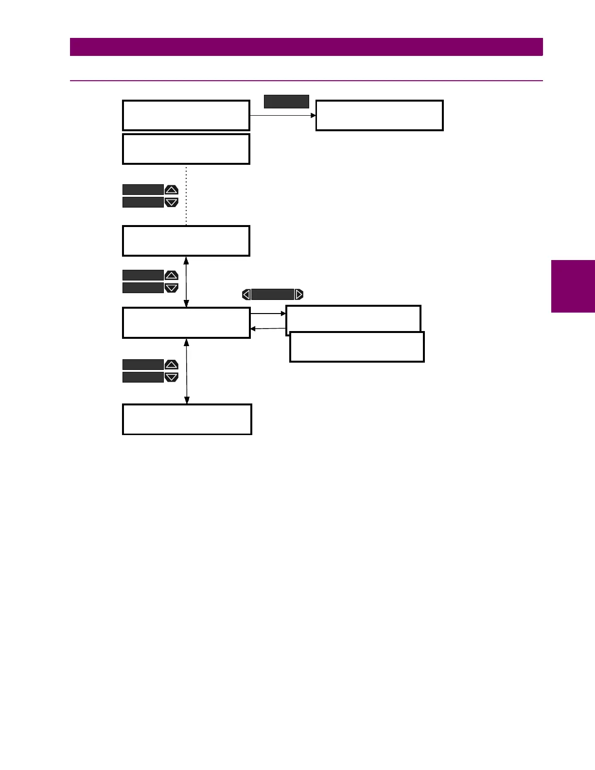
4.3.7 DATA LOGGER
Figure 4–20: SETPOINTS PAGE 2 – SYSTEM SETUP / DATA LOGGER
•
STOP DATA LOG 1 / 2:
The data logger operation is only configurable over the serial port using PQMPC
or other third party software. On occasions it may be necessary to stop the data loggers using the PQM
keypad and then a computer to extract the logged information. The STOP DATA LOG 1 and 2 setpoints
allow the user to stop the respective data log. These setpoints also display the current status of the respec-
tive data logger. Refer to the Appendix for a detailed description of the data logger implementation.
]] SETPOINTS
]] S2 SYSTEM SETUP
]] SETPOINTS
]] S3 OUTPUT RELAYS
SETPOINT
] CURRENT/VOLTAGE
] CONFIGURATION
STOP DATA LOG 1:
NO (STOPPED)
STOP DATA LOG 2:
NO (STOPPED)
Range: NO, YES
] DATA LOGGER
]
] PULSE INPUT
]
] END OF PAGE S2
]
Range: NO, YES
MESSAGE
MESSAGE
MESSAGE
MESSAGE
MESSAGE
MESSAGE
MESSAGE

 Loading...


