GE Power Management PQM Power Quality Meter 2-1
2 INSTALLATION 2.1 PHYSICAL
2
2 INSTALLATION 2.1 PHYSICAL 2.1.1 MOUNTING
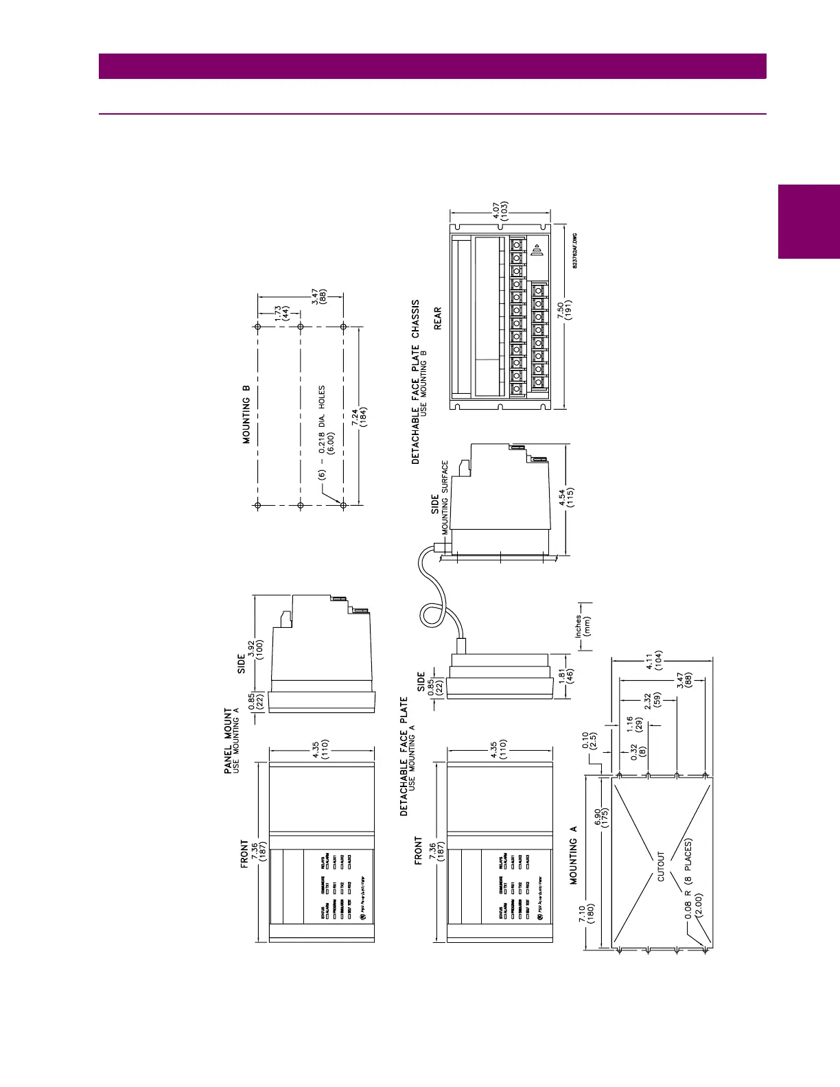
Physical dimensions and required cutout dimensions for the PQM are shown below. Once the cutout and
mounting holes are made in the panel, use the eight #6 self-tapping screws provided to secure the PQM.
Mount the unit on a panel or switchgear door to allow operator access to the keypad and indicators.
Figure 2–1: PHYSICAL DIMENSIONS

 Loading...


