GE Power Management PQM Power Quality Meter 1-5
1 OVERVIEW 1.2 STANDARD FEATURES
1
1.2.3 OPTIONAL FEATURES
a) TRANSDUCER OPTION
Four isolated 4 to 20 mA (or 0 to 1 mA depending on the installed option) analog outputs are provided that can
replace up to eight transducers. The outputs can be assigned to any measured parameters for direct interface
to a PLC.
One 4 to 20 mA analog input is provided to accept a transducer output for displaying information such as tem-
perature or water level.
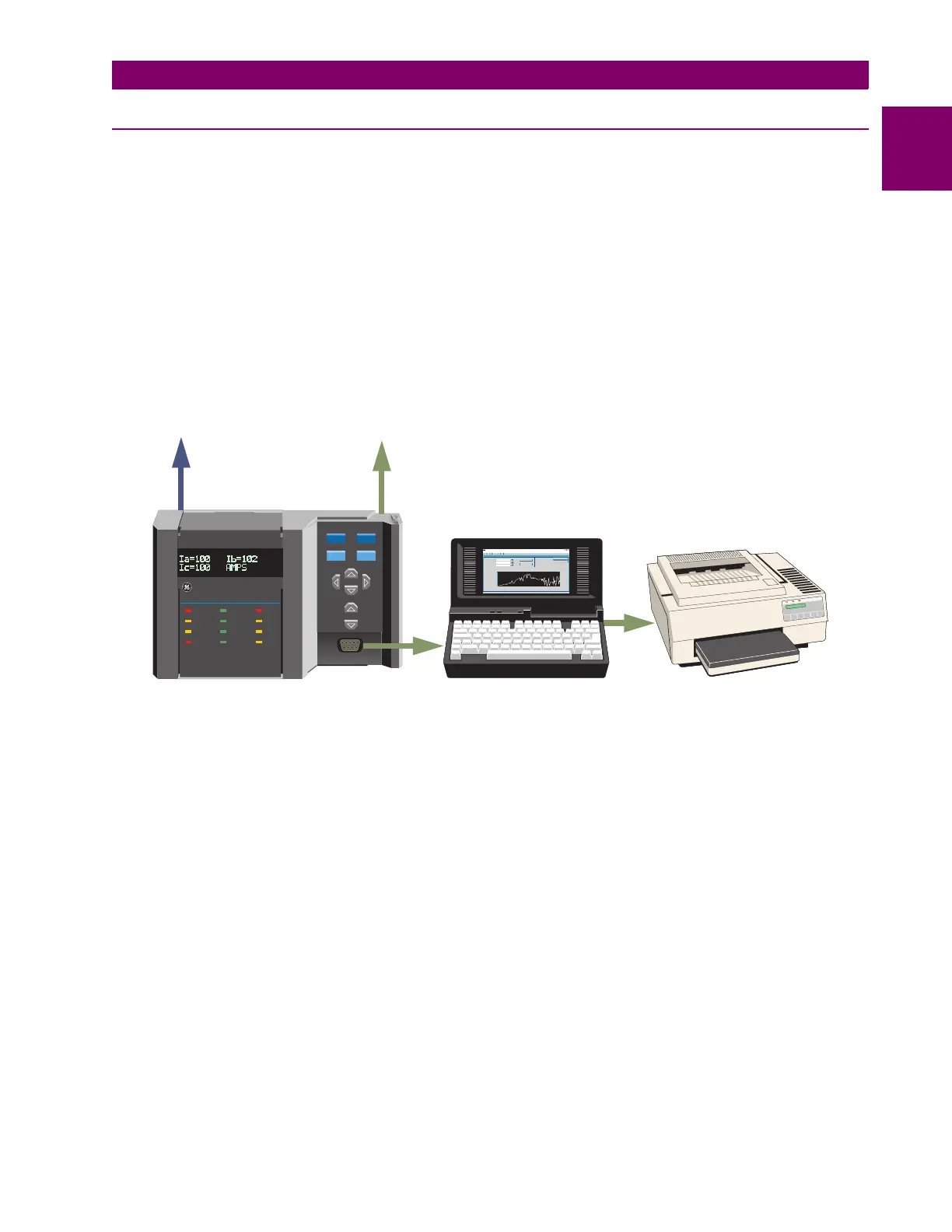
An additional rear RS485 communication port is provided for simultaneous monitoring by process, instrument,
electrical, or maintenance personnel.
Figure 1–4: ADDITIONAL COMMUNICATION PORT
STATUS COMMUNICATE RELAYS
VALUE
MESSAGE
ACTUAL
SETPOINT
RESET
STORE
SIMULATION
ALARM
SELF TEST
PROGRAM
TX2
TX1
RX2
RX1
AUX2
ALARM
AUX3
AUX1
823779A7.CDR
•Data monitoring
•Problem diagnosis
•Event records
•Trending
•Report printing
Main plant
control/monitoring
communication
interface
RS485 RS485
RS232
Print reports
Use 2nd/3rd comm ports for simultaneous
access by electrical, maintenance,
process, instrumentation personnel
for
PQMWindows Application - PQM
File
Setpoint
Actual
Communication
Help
ForHelp, press F1
Actual- Chart Recorder
OK
Cancel
Seconds(Elapsed Time)
TrendingChart
RUN
PRINT
PQM Power Quality Meter

 Loading...


