2-16 PQM Power Quality Meter GE Power Management
2.2 ELECTRICAL 2 INSTALLATION
2
access terminals are not shorted. When the access terminals are open, all actual and setpoint values can
still be accessed for viewing; however, if an attempt is made to store a new setpoint value, the message
SETPOINT ACCESS DISABLED
is displayed and the previous setpoint remains intact. In this way, all of the pro-
grammed setpoints remain secure and tamper proof.
•
SELECT ANALOG OUTPUT:
This switch selection allows each analog output to be multiplexed into two
outputs. If the switch is active, the parameter assigned in setpoint
S2 SYSTEM SETUP \ ANALOG OUTPUT
1 \ ANALOG OUTPUT 1 ALT
determines the output level. If the switch is not active, the parameter assigned in
setpoint
S2 SYSTEM SETUP \ ANALOG OUTPUT 1 \ ANALOG OUTPUT 1 MAIN
is used. See Sections 2.2.7: ANA-
LOG OUTPUTS (OPTIONAL) below and 4.3.2: ANALOG OUTPUTS on page 4–21 for additional details.
•
SELECT ANALOG INPUT:
This switch selection allows the analog input to be multiplexed into two inputs.
If the switch is active, the parameter assigned in setpoint
S2 SYSTEM SETUP \ ANALOG INPUT ALT
is used to
scale the input. If the switch is not active, the parameter assigned in setpoint
S2 SYSTEM SETUP
\ ANALOG INPUT \ ANALOG INPUT MAIN
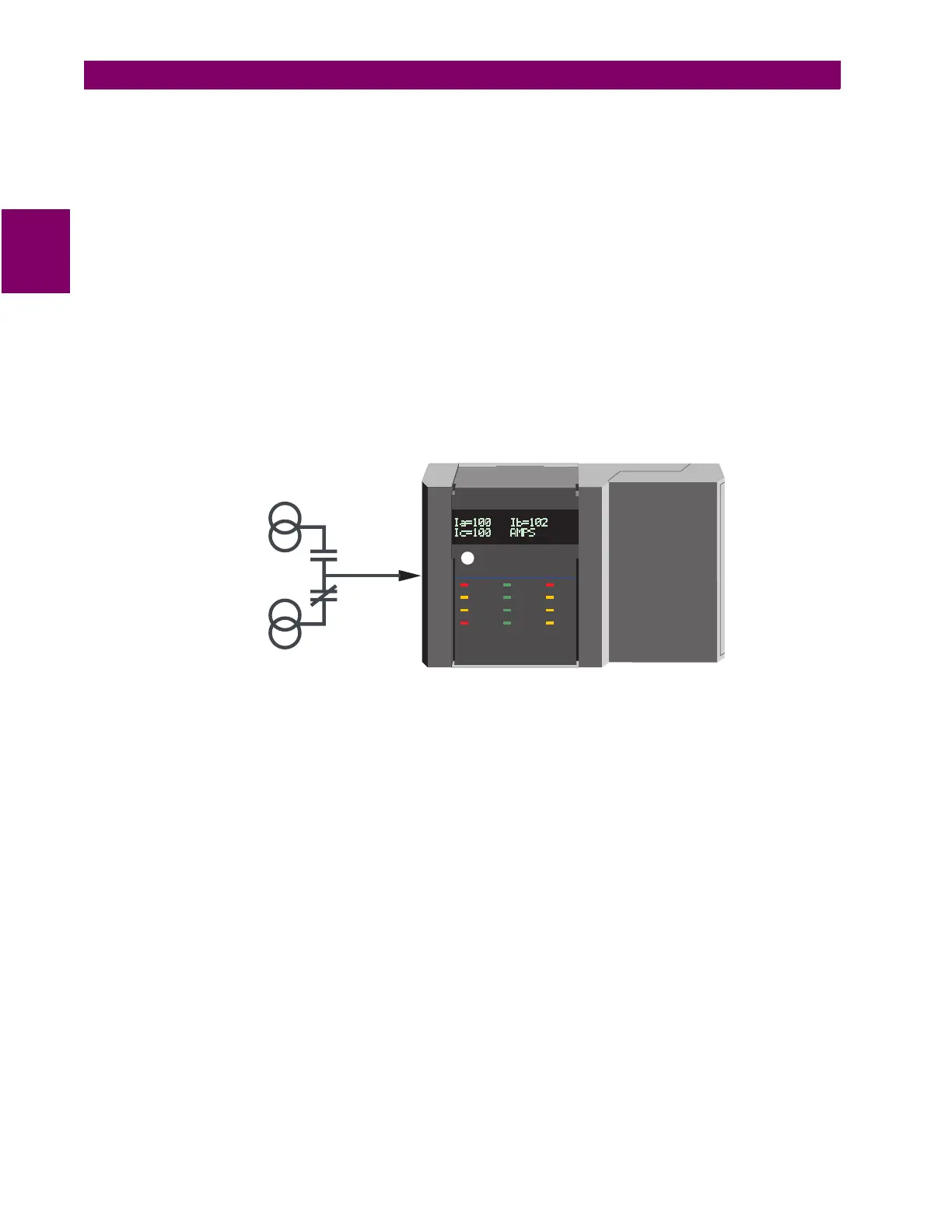
is used. If a relay is assigned in
S2 SYSTEM SETUP \ ANALOG INPUT
\ ANALOG IN MAIN/ALT SELECT RELAY
, that relay energizes when the switch is active and de-energizes when
the switch is not active, thus providing the ability to feed in analog inputs from two separate sources as
shown in the figure below. See Sections 2.2.8: ANALOG INPUT (OPTIONAL) below and 4.3.3: ANALOG
INPUT on page 4–25 for additional details.
Figure 2–12: ANALOG INPUT MULTIPLEXING
•
AUX 1 / 2 / 3 RELAY
: When a switch input is assigned to an AUX relay, a closure on the switch input
causes the programmed auxiliary relay to change state. This selection is available only if the Control (C)
option is installed.
•
CLEAR ENERGY
: When a switch input is assigned to CLEAR ENERGY, a closure on the switch input will
clear all Energy data within the PQM.
•
CLEAR DEMAND
: When a switch input is assigned to CLEAR DEMAND, a closure on the switch input will
clear all Demand data within the PQM.
823803A3.CDR
PQM AUX
RELAY
PQM AUX
RELAY
ANALOG
INPUT
ANALOG
INPUT
4-20 mA
transducer
4-20
mA
transducer
4-20 mA
transducer
4-20
mA
transducer
STATUS COMMUNICATE RELAYS
PQM Power Quality Meter
SIMULATION
ALARM
SELF TEST
PROGRAM
TX2
TX1
RX2
RX1
AUX2
ALARM
AUX3
AUX1
g

 Loading...


