7-52 PQM Power Quality Meter GE Power Management
7.3 MODBUS MEMORY MAP 7 MODBUS COMMUNICATIONS
7
FLASH
MESSAGE
continued
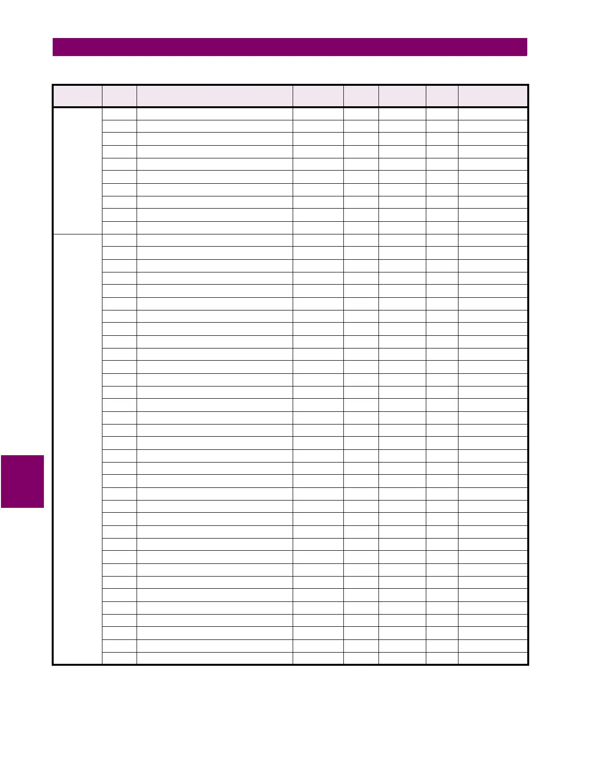
121D Flash message characters 27 and 28 32 to 127 1 ASCII F10 ""
121E Flash message characters 29 and 30 32 to 127 1 ASCII F10 ""
121F Flash message characters 31 and 32 32 to 127 1 ASCII F10 ""
1220 Flash message characters 33 and 34 32 to 127 1 ASCII F10 ""
1221 Flash message characters 35 and 36 32 to 127 1 ASCII F10 ""
1222 Flash message characters 37 and 38 32 to 127 1 ASCII F10 ""
1223 Flash message characters 39 and 40 32 to 127 1 ASCII F10 ""
1224 Reserved
to
↓
↓
↓
↓
↓
↓
125F Reserved
DATA
LOGGER
1260 Log 1 Interval (high) 1 to 86400 1 s F3 3600
1261 Log 1 Interval (low) 1 to 86400 1 s F3 3600
1262 Log 2 Interval (high) 1 to 86400 1 s F3 3600
1263 Log 2 Interval (low) 1 to 86400 1 s F3 3600
1264 Log 1 Mode 0 to 1 1 --- F32 0 = RUN TO FILL
1265 Log 2 Mode 0 to 1 1 --- F32 0 = RUN TO FILL
1266 Log Size Determination 0 to 1 1 --- F33 0 = AUTOMATIC
1267 Log 1 Size 0 to 100 1 % F1 0%
1268 Data Log Memory Access Block Number 0 to 511 1 --- F1 0
1269 Stop Data Log 1 0 to 1 1 --- F31 0=NO
126A Stop Data Log 2 0 to 1 1 --- F31 0=NO
126B Reserved
to
↓
↓
↓
↓
↓
↓
126F Reserved
1270 Ia Log Assignment 0 to 3 1 --- F34 0 = NONE
1271 Ib Log Assignment 0 to 3 1 --- F34 0 = NONE
1272 Ic Log Assignment 0 to 3 1 --- F34 0 = NONE
1273 Iavg Log Assignment 0 to 3 1 --- F34 0 = NONE
1274 In Log Assignment 0 to 3 1 --- F34 0 = NONE
1275 I Unbalance Log Assignment 0 to 3 1 --- F34 0 = NONE
1276 Van Log Assignment 0 to 3 1 --- F34 0 = NONE
1277 Vbn Log Assignment 0 to 3 1 --- F34 0 = NONE
1278 Vcn Log Assignment 0 to 3 1 --- F34 0 = NONE
1279 Vpavg Log Assignment 0 to 3 1 --- F34 0 = NONE
127A Vab Log Assignment 0 to 3 1 --- F34 0 = NONE
127B Vbc Log Assignment 0 to 3 1 --- F34 0 = NONE
127C Vca Log Assignment 0 to 3 1 --- F34 0 = NONE
127D Vlavg Log Assignment 0 to 3 1 --- F34 0 = NONE
127E V Unbalance Log Assignment 0 to 3 1 --- F34 0 = NONE
127F Pa Log Assignment 0 to 3 1 --- F34 0 = NONE
1280 Qa Log Assignment 0 to 3 1 --- F34 0 = NONE
1281 Sa Log Assignment 0 to 3 1 --- F34 0 = NONE
1282 PFa Log Assignment 0 to 3 1 --- F34 0 = NONE
1283 Pb Log Assignment 0 to 3 1 --- F34 0 = NONE
Table 7–10: PQM MEMORY MAP (Sheet 38 of 40)
GROUP ADDR
(HEX)
DESCRIPTION RANGE STEP
VALUE
UNITS and
SCALE
FORMAT FACTORY DEFAULT
Notes: * Data type depends on the Command Operation Code. ** Any valid Actual Values or Setpoints address.
*** Maximum Setpoint value represents “OFF”. **** Minimum Setpoint value represents “OFF”.
***** Maximum Setpoint value represents “UNLIMITED”.

 Loading...


