7-54 PQM Power Quality Meter GE Power Management
7.3 MODBUS MEMORY MAP 7 MODBUS COMMUNICATIONS
7
to
↓
↓
↓
↓
↓
↓
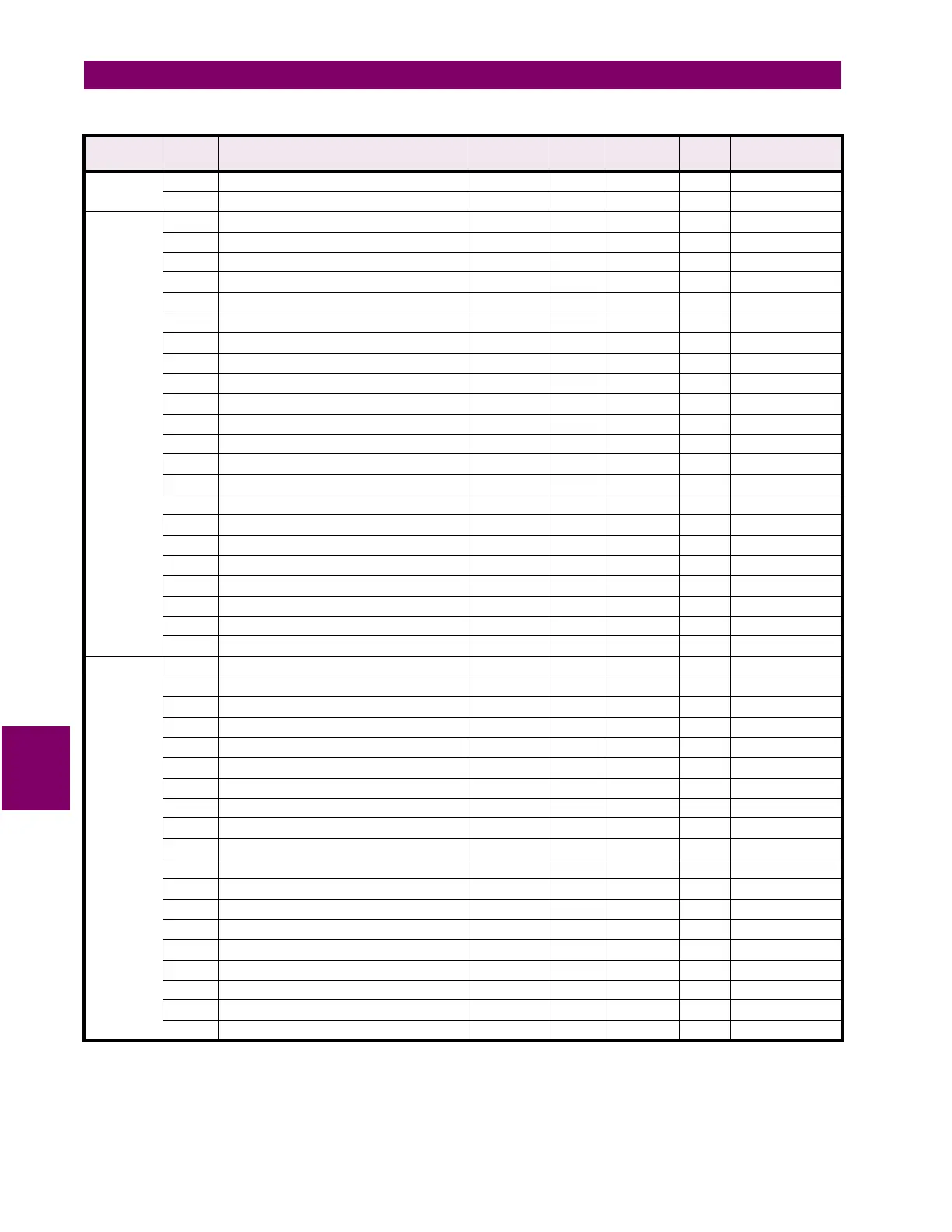
12CF Reserved
TRACE
MEMORY
12D0 Trace Memory Usage 0 to 2 1 --- F37 0=1x36 cycles
12D1 Trace Memory Trigger Mode 0 to 1 1 --- F38 0=ONE SHOT
12D2 Ia Overcurrent Trigger Level 1 to 151*** 1 % CT F1 151=OFF
12D3 Ib Overcurrent Trigger Level 1 to 151*** 1 % CT F1 151=OFF
12D4 Ic Overcurrent Trigger Level 1 to 151*** 1 % CT F1 151=OFF
12D5 In Overcurrent Trigger Level 1 to 151*** % CT F1 151=OFF
12D6 Va Overvoltage Trigger Level 20 to 151*** 1 % VT F1 151=OFF
12D7 Vb Overvoltage Trigger Level 20 to 151*** 1 % VT F1 151=OFF
12D8 Vc Overvoltage Trigger Level 20 to 151*** 1 % VT F1 151=OFF
12D9 Va Undervoltage Trigger Level 20 to 151*** 1 % VT F1 151=OFF
12DA Vb Undervoltage Trigger Level 20 to 151*** 1 % VT F1 151=OFF
12DB Vc Undervoltage Trigger Level 20 to 151*** 1 % VT F1 151=OFF
12DC Switch Input A Trigger 0 to 2 1 --- F39 0=OFF
12DD Switch Input B Trigger 0 to 2 1 --- F39 0=OFF
12DE Switch Input C Trigger 0 to 2 1 --- F39 0=OFF
12DF Switch Input D Trigger 0 to 2 1 --- F39 0=OFF
12E0 Trace Memory Trigger Delay 0 to 30 1 cycles F1 0 cycles
12E1 Trace Memory Waveform Selection 0 to 6 1 --- F40 0=Ia
12E2 Trace Memory Trigger Relay 0 to 4 1 --- F29 0=OFF
12E3 Reserved
to
↓
↓
↓
↓
↓
↓
12EF Reserved
PRODUCT
OPTIONS
12F0 Product Options Upgrade 0 to 23 1 --- F116 0
12F1 Product Modifications Upgrade MOD1 0 to 999 1 --- F1 0
12F2 Product Modifications Upgrade MOD2 0 to 999 1 --- F1 0
12F3 Product Modifications Upgrade MOD3 0 to 999 1 --- F1 0
12F4 Product Modifications Upgrade MOD4 0 to 999 1 --- F1 0
12F5 Product Modifications Upgrade MOD5 0 to 999 1 --- F1 0
12F6 Passcode Input 1 32 to 127 1 --- F10 32
12F7 Passcode Input 2 32 to 127 1 --- F10 32
12F8 Passcode Input 3 32 to 127 1 --- F10 32
12F9 Passcode Input 4 32 to 127 1 --- F10 32
12FA Passcode Input 5 32 to 127 1 --- F10 32
12FB Passcode Input 6 32 to 127 1 --- F10 32
12FC Passcode Input 7 32 to 127 1 --- F10 32
12FD Passcode Input 8 32 to 127 1 --- F10 32
12FE Passcode Input 9 32 to 127 1 --- F10 32
12FF Passcode Input 10 32 to 127 1 --- F10 32
1300 Reserved
to
↓
↓
↓
↓
↓
↓
131F Reserved
Table 7–10: PQM MEMORY MAP (Sheet 40 of 40)
GROUP ADDR
(HEX)
DESCRIPTION RANGE STEP
VALUE
UNITS and
SCALE
FORMAT FACTORY DEFAULT
Notes: * Data type depends on the Command Operation Code. ** Any valid Actual Values or Setpoints address.
*** Maximum Setpoint value represents “OFF”. **** Minimum Setpoint value represents “OFF”.
***** Maximum Setpoint value represents “UNLIMITED”.

 Loading...


