om 5184516-100 Rev. 5 11-8
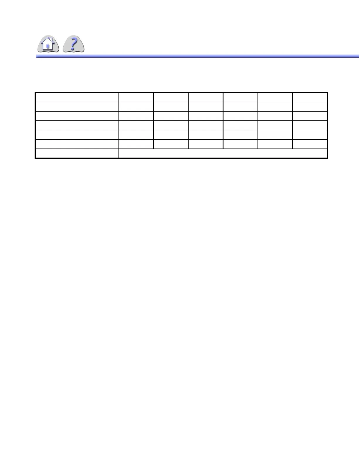
TABLE 11-13
KVA LOAD CHARACTERISTICS 80KW
4-2X–Ray Interlock Systems
”Deadman’s switch” X–ray Control Safety Switch
X–ray emmision is terminated instantly when you release the x–ray control radiog-
raphy pushbutton.
A special safety circuit uses a signal from second trigger (radiographic exposure)
controls transmitted directly via relay contacts to the control circuit of the power
inverter. If the microprocessor does not stop x–ray emission after a delay of sev-
eral milliseconds, inverter operation is inhibited. In this case, a fault signal is sent
to the control circuits of the generator.
X–ray Tube Housing Overheat Interlock
If the factory–adjusted temperature of the tube housing goes higher than the per-
missible level, x–ray emission is terminated.
If it occurs, ask the service Refer to troubleshooting chart.
Phase 3 3 3 3 3 3
Nominal line Voltage (Vac) 380 400 420 440 460 480
Voltage Range (Vac) +/–10% +/–10% +/–10% +/–10% +/–10% +/–10%
Momentary Line Current (Amp) 190 180 170 163 156 150
Continuous Line Current (Amp) 7 6.7 6.2 6 5. 7 5.5
Power demands (kVA) 125 125 125 125 125 125
Frequency 47 / 53Hz and 57/63Hz
FOR TRAINING PURPOSES ONLY!
NOTE: Once downloaded, this document is UNCONTROLLED, and therefore may not be the latest revision. Always confirm revision status against a validated source (ie CDL).