GFK-1504K Chapter 7 Discrete Input Modules 7-37
7
IC200MDL635
Input Module, 48VDC Pos/Neg Logic Grouped 16 Points
Field Wiring
Terminal Connection Terminal Connection
A1 Input 1 B1 No connection
A2 Input 2 B2 No connection
A3 Input 3 B3 No connection
A4 Input 4 B4 No connection
A5 Input 5 B5 No connection
A6 Input 6 B6 No connection
A7 Input 7 B7 No connection
A8 Input 8 B8 No connection
A9 Input 9 B9 No connection
A10 Input 10 B10 No connection
A11 Input 11 B11 No connection
A12 Input 12 B12 No connection
A13 Input 13 B13 No connection
A14 Input 14 B14 No connection
A15 Input 15 B15 No connection
A16 Input 16 B16 No connection
A17 Inputs 1-8 Common B17 No connection
A18 Inputs 9-16 Common B18 No connection
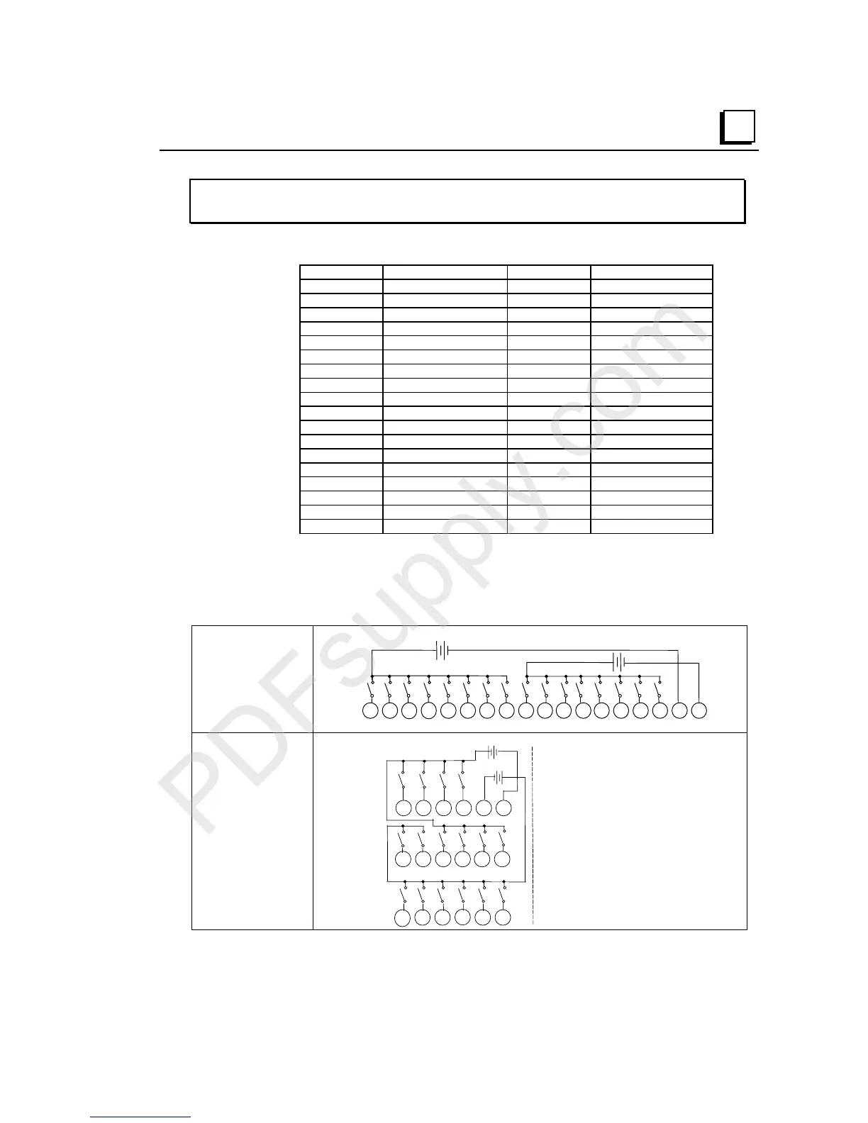
The 16 inputs form two groups of 8. Each group has a common connection. Each
group may be wired for positive or negative logic inputs. If additional bussed
terminals are needed, the B terminals can be made available using a shorting bar.
The shorting bar has a maximum current-carrying capacity of 2 Amps per point. See
chapter 2 for additional information about using the shorting bar.
Wiring Connections
for Carriers with Two
Rows of Terminals
IC200CHS002, 005
IC200CHS012, 015
1 2 3 4 5 6 7 8 9 11 12 13 14 15 16 17 1810
I1 I2 I3 I4 I5 I6 I7 I8 I9 I10 11 I12 I13 I14 I15 I16
A
+
-
(+)
(-)
+
-
(+)(-)
-
(+)
-
(+)
Wiring Connections
for Carriers with
Three Rows of
Terminals
IC200CHS001, 022, 025
IC200CHS011
A
123456
13
14 15 16 17 18
789 111210
I1 I2 I3 I4 I5 I6
I7
I8
I9 I10 I11
I12
I16
+
-
(+)
-
I13 I14 I15
+
-
(+)
-